


MAYCO ST-45HRM CE PUMP — OPERATION & PARTS MANUAL — REV. #0 (02/23/04) — PAGE 3
TABLE OF CONTENTS
MAYCO ST-45HRM CE
CONCRETE PUMP
Here’s how To Get Help.............................................2
Table of Contents ......................................................3
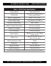
Pump Specifications..................................................4
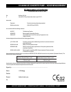
Engine Specifications ................................................5
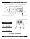
Dimensions .............................................................. 6
Noise Measurement..................................................7
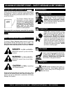
Safety Message Alert Symbols ............................ 8-9
Rules for Safe Operation .................................. 10-12
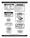
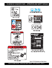
Operation and Safety Decals ............................ 13-15
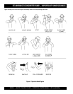
Important Hand Signals ..........................................16
General Information .......................................... 17-18
How it Works............................................................19
Pump Components ........................................... 20-21
Control Box Components ........................................22
Engine Components ...............................................23
Operating Procedures....................................... 24-28
Inspection .......................................................... 29-31
Initial Start-Up Procedure ................................. 32-35
Trailer Safety Guidelines ................................... 36-37
Towing Information ............................................ 38-41
Braking System ................................................. 42-47
Troubleshooting (Brake System).............................48
Torque Tables ..........................................................49
Maintenance (Pump) ........................................ 50-58
Hydraulic Hose Connections ............................. 59-61
Manifold Port Locations ..........................................62
Appendix — Concrete Mix Information ............. 64-65
Appendix — Slump Test Procedure ........................66
Troubleshooting (Engine) ........................................67
Troubleshooting (Hydraulic System) .......................68
Troubleshooting (Electrical System) .......................69
Appendix — Recommended
Shotcrete System ..........................70-71
Appendix — Recommended
Shotcrete Accessories ...................72-73
Explanation Of Code In Remarks Column ..............74
Suggested Spare Parts ...........................................75
Specification and part
number are subject to
change without notice.
NOTE
PARTS ILLUSTRATIONS
Decal Placement ................................................76-77
Safet Grids Assembly.........................................78-79
Hub and Drum Assembly ...................................80-81
Brake Components Assembly............................82-83
Towing Coupler Assembly ..................................84-85
Hopper Assembly ............................................... 86-87
Hopper Attachment Assembly ...........................88-89
Hopper Interior Assembly ..................................90-91
Shuttle Cylinder Assembly .................................92-93
Fuel and Hydraulic Tank Assembly ....................94-97
Front Cover Assembly........................................98-99
Heat Exchanger Assembly .............................100-101
Engine and Frame Assembly .........................102-103
Throttle and Water Filter Assembly ................104-105
Hydraulic Pump Assembly .............................106-107
Lubrication Pistons Assembly ........................108-109
Electrical System Assembly ...........................110-111
Accumulator Assembly...................................112-113
Manifold Assembly .........................................114-115
Remixer Control Assembly ............................116-117
Battery Assembly ...........................................118-119
Lubrication Panel ...........................................120-121
Control Box Interior Door Assembly ..............122-123
Control Box Mounting Assembly ...................124-125
Control Box Assembly ...................................126-127
Control Box Door Wiring Diagram ......................... 128
Control Box Interior Wiring Diagram ..................... 129
Terminal Block Wiring Diagram ............................. 130
Control Box Electrical Diagram ......................132-134
Hydraulic Diagram ............................................... 135
Optional Radio Control.......................................... 136
Wiring Diagram (Tail Lights) ................................. 137
Terms and Conditions Of Sale — Parts ................ 138
Mayco Pump Warranty .......................................... 139