


DIGITAL CONTROL PANEL COMPONENTS
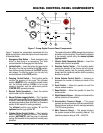
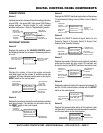
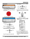
Screen 1
Indicates the various modes of the switch settings. Monitors
engine RPM - Idle speed 900, High speed 2350. Battery
charge indicator - Normal charge 13+ volts. Indicates
electrical malfunction - Refer to Troubleshooting section.
SECONDARY SCREENS
Screen 2
Displays the position of the switch
by indicating whether the increase or decrease position is
on or off.
Screen 3
Displays the number of hours the engine and pump
have been used and the number of faults the pump has
registered. All three indicators can be reset to zero by the
RESET switch on the control panel.
Screen 4
Displays the number of strokes the main hydraulic cylinders
have gone through. This indicator can be reset to zero by
the RESET switch on the control panel.
LS 600 OFF
0000 ENG RPM
BATTERY 12.5 V
LOW OIL PSI
1
INDICATES
STATUS OF PUMP
(ONOR OFF)
INDICATES
ENGINE RPM
INDICATES
BATTERY
CHARGE
INDICATES
ELECTRIC
MALFUNCTION
FLOW DEC OFF
FLOW INC ON
2
INDICA
TES VOLUME
SWITCH
IS NOT IN
THE-POSITION
INDICATES VOLUME
SWITCH IS IN THE
+ POSITION
E HRS: 00000.0
PMP HRS: 00000.0
FAULTS: 00000000
RESET TO CLEAR
3
INDICA
TES NO.
OF
HOURS
ENGINE
HAS
BEEN
USED
MESSAGE OR
INSTRUCTION
INDICATES
NO.
OF HOURS
PUMP HAS
BEEN USED
INDICATES NO.
OF FAULTS
DETECTED
STROKE CTR: 0000
PRESS RESET TO
ZERO STROKE CTR
4
INDICATES A
RUNNING
COUNT
OF
NO.
OF STROKES
MESSAGE OR
INFORMA
TION
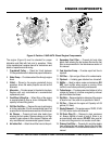
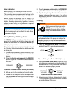
Screen 5
Displays the ON/OFF electrical signal status of the various
12 volt solenoids (Swing A circuit, Main A circuit, Main B
circuit).
Screen 6
Displays the ON/OFF electrical signal status for the
Proximity Switch A, Proximity Switch B, Engine Fuel
Solenoid, and Unloader Solenoid.
Screen 7
Displays the number of times the main hydraulic cylinders
stroke and the yards per hour output. This indicator can
be reset to zero by the RESET switch on the control panel
Screen 8
Displays the electrical status of the engine fuel solenoid. To
test the 12-Volt solenoid status, activate with the RESET
switch on the control panel.
Screen 9
Displays the communication status of the (optional) radio
remote control. To activate a new remote control connection,
use the reset switch on the control panel.
INDICATES
SWING A
CIRCUIT IS OFF
INDICATES
MAIN A
CIRCUIT IS
OFF
INDICA
TES
MAIN
B
CIRCUIT
IS OFF
SWING A OFF
MAIN A OFF
MAIN B OFF
5
INDICATES
PROXIMITYA
CIRCUIT IS OFF
INDICATES
PROXIMITY B
CIRCUIT IS ON
INDICATES
FUEL
SOLENOID
CIRCUIT IS OFF
INDICATES
UNLOADER
CIRCUIT IS OFF
PROX A OFF
PROX BON
FUEL SOL OFF
UNLOADER OFF
6
INDICATES
THROTTLE
IS ON
INDICATES
THE
NUMBER OF
STROKES
INDICATES THE
NO. OF STROKES
PER MINUTE
INDICATES THE
NO. OF YARDS
PER HOUR
THROTTLE ON
STROKES: 20
STROKES/MIN 8.2
YDS/HR 10.7
7
INSTRUCTION
OR
MESSAGE
INDICA
TES THE
FUEL
SOLENOID
IS
OFF
TO TEST FUEL
SOL PRESS RESET
FUEL SOL OFF
8
INDICATES
THAT RADIO
REMOTE IS
ON
INSTRUCTION
OR
MESSAGE
RADIO ADDRESS
COMMUNICATING
PRESS RESET TO
LEARN ANEW ONE
9