


74D3000
6
BLDV7 Series Gas Fireplace
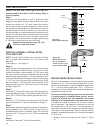
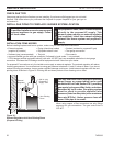
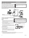
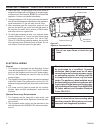
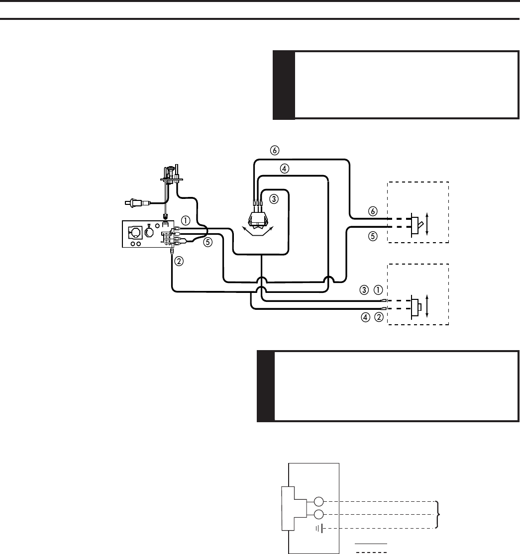
A remote wall switch and up to fifteen (15) feet of 18 Ga. wire
may be used with this appliance. Attach the wall switch in a
junction box at the desired location on the wall. Figure 34. Do
not extend beyond the wall switch wire length provided.
Figure 34 -
Wiring Diagram for Wall Switch
Electrical connections should only be performed
by a qualified, licensed electrician. Main power
supply must be turned off before connecting fans
to the main electrical power supply or performing
service.
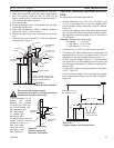
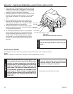
1. Before installing the blower, wire the receptacle into an
electrical circuit. This should be done before framing
the fireplace. Wire with minimum 60° C wire in accor-
dance with prevailing codes.
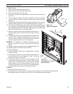
. Remove the external junction box cover by removing the
screw from the left side of the outside firebox wall. Junc-
tion box was installed at the factory.
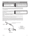
3. The junction box cover has a factory installed “romex” style
strain relief connector. After connecting the wires, route
the wire leads through this connector. Refer to the wiring
diagram in Figure 35.
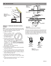
1. Always turn off the gas supply and allow the unit to cool
down before proceeding.
. Clean the inside of the firebox (wall and floor), where the
blower and wires will be installed. Make sure the firebox
wall and floor are clean and dry before mounting the blow-
er.
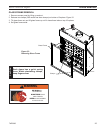
1. Remove the lower access panel by pulling up and away from unit.
. Remove glass frame by releasing the two () latches (500 Model has three (3) latches) below the
firebox opening and lifting glass frame up and away from unit.
FP1912
Junction box wiring
8/08
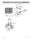
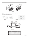
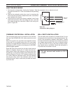
Figure 35 -
Junction Box Wiring Diagram
10V AC
60Hz
Factory Supplied
Not Supplied
ON
OFF
OPTIONAL REMOTE
WALL SWITCH
ON
OFF
OPTIONAL REMOTE
CONTROL RECEIVER
PILOT
HI
LO
ON
OFF
TH
TP
TH/TP
ON
OFF
RS
FP1980
Dv wiring diagram