


74D3000
14
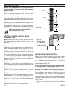
BLDV7 Series Gas Fireplace
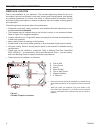
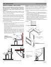
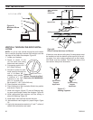
When using twist lock pipe it is not necessary to use sealant on the joints. The only areas of the
venting system that need to be sealed with high temperature silicone sealant are the sliding joints
of any telescopic vent section used in the system.
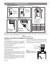
To join twist lock pipes together, simply align the beads of the male end with the grooves of the fe-
male end, twisting the pipe until the flange on the female end contacts external flange on the male
end. It is recommended that you secure the joints with three (3) sheet metal screws, however, this
is not mandatory with twist lock pipe. Figure 9
To make it easier to assembly the joints, we suggest putting a lubricant (Vaseline or similar) on the
male end of the twist lock pipe prior to assembly.
TWL100
Twist Lock Pipe
3/12/99 djt
Male End
Female End
Screw Holes
TWL100
Figure 9 -
Twist-lock Pipe Joints
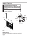
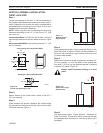
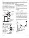
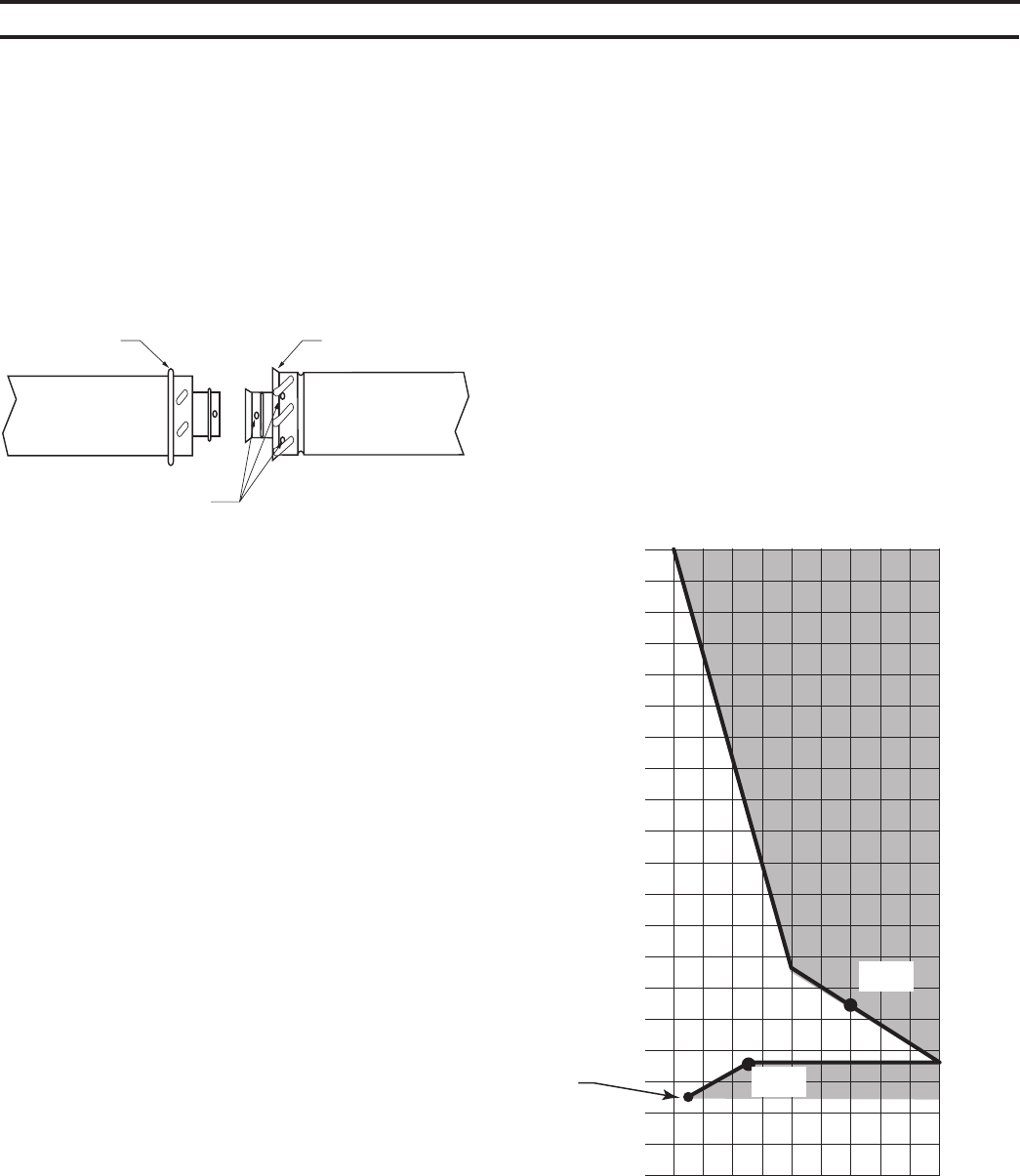
The Vent Graph should be read in conjunction with the
following vent installation instructions to determine the re-
lationship between the vertical and horizontal dimensions
of the vent system.
1. Determine the height of the center of the horizontal
vent pipe exiting through the outer wall. Using this di-
mension on the Sidewall Vent Graph, Figure 10, locate
the point intersecting with the slanted graph line.
. From the point of this intersection, draw a vertical line
to the bottom of the graph.
3. Select the indicated dimension, and position the fire-
place in accordance with same.
If the vertical dimension from the floor of the unit is 11’ (3.4
m) the horizontal run to the face of the outer wall must not
exceed 14’ (4.3 m).
If the vertical dimension from the floor of the unit is 7’ (.1
m), the horizontal run to the face of the outer wall must not
exceed 7’ (.1 m).
Page 18
FP2337
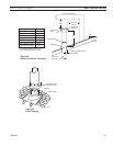
sidewall vent graph
2 4 6 8 10 12 14 16 18 20
40
38
36
34
32
30
28
26
24
22
20
18
16
14
12
10
8
6
4
2
Figure 10 -
Rear Wall Venting Graph
Horizontal dimension from the finished outside wall
to the center of the pipe on the fireplace
Vertical Dimension From the Floor of Unit to the
Center of the Horizontal Vent Pipe