


74D3000
19
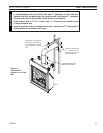
BLDV7 Series Gas Fireplace
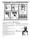
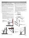
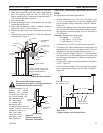
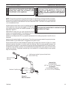
. Remove soil to a depth of approximately 16” (406 mm)
below base of snorkel. Install drain pipe. Install window
well (not supplied). Refill hole with 1” (305 mm) of
coarse gravel leaving a clearance of approximately 4”
(10 mm) below snorkel. Figure 21
3. Install vent system.
4. Ensure a watertight seal is made around the vent pipe
coming through the wall.
5. Apply high temperature sealant caulking (supplied)
around the 4” and 7” snorkel collars.
6. Slide the snorkel into the vent pipes and secure to the
wall.
7. Level the soil so as to maintain a 4” (10 mm) clear
ance
below snorkel. Figure 21
BG402a
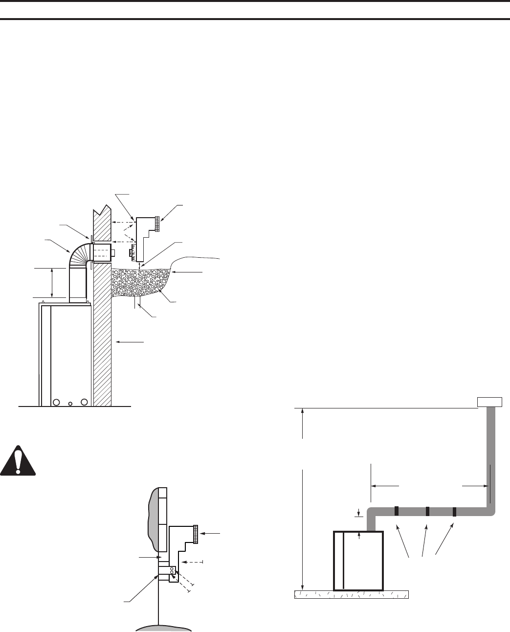
Top Vent
Below grade installation
1/26/00 djt
Firestop
7” Pipe
7TDVSNORK
(Snorkel)
4” (10 mm)
C l e a r a n c e
Min.
Window
Well
Gravel
Drain
BG40a
Figure 21 -
Below Grade Installation
*A minimum of 4” (610 mm) verti-
cal pipe must be installed when
using the 7TDVSNORK Kit.
4” (610 mm)
Minimum*
Screws
Foundation Wall
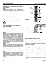
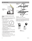
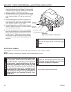
If the foundation is re-
cessed, use recess
brackets (not supplied)
for securing lower por-
tion of the snorkel. Fas-
ten brackets to wall
first, then secure
to snorkel with
self drilling #8 x
1/ sheet metal
screws. It will be
necessary to ex-
tend vent pipes
out as far as the
protruding wall
face. Figure 22
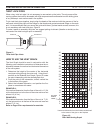
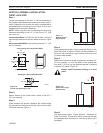
his gas fireplace has been approved for:
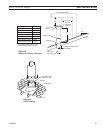
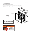
• Vertical installations up to 40’ (1 m) in height. Up to
a 10’ (3 m) horizontal vent run can be installed within
the vent system using a maximum of two 90° elbows.
Figure 23
• Up to two 45° elbows may be used within the horizontal
run. For each 45° elbow used on the horizontal plane,
the maximum horizontal length must be reduced by
18” (450 mm).
Maximum horizontal length:
No elbows = 10’ (3 m)
1 x 45° elbow = 8.5’ (.6 m)
x 45° elbows = 7’ (.1 m)
• A minimum of an 8’ (.5 m) vertical rise is required.
• Two sets of 45° elbow offsets may be used within the
vertical sections. From 0 to a maximum of 8’ (.5 m) of
vent pipe can be used between elbows. Figure 23
• 7DVCS supports offsets. Figure 27. This application
will require that you first determine the roof pitch and
use the appropriate starter kit. (Refer to Venting Com-
ponents List)
• The maximum angular variation allowed in the system
is 70°. Figure 24
• For the minimum height of the vent above the highest
point of penetration through the roof refer to Page 1,
Figure 28.
Max. Height 40’ (12 m)
Min. Height 8’ (2 mm)
Max. 10’ (3 m)
12” (305 mm)
Min.
Support Straps
Every 3' (914 mm)
FP1183
Figure 23 -
Support Straps for Horizontal Runs
BG401
Snorkel
2/10/99 djt
Snorkel
Wall
Screws
Foundation
Recess
Watertight
Seal Around
PIpe
Sheet Metal
Screws
BG401
Figure 22 -
Snorkel Installation,
Recessed Foundation