


5
10.4
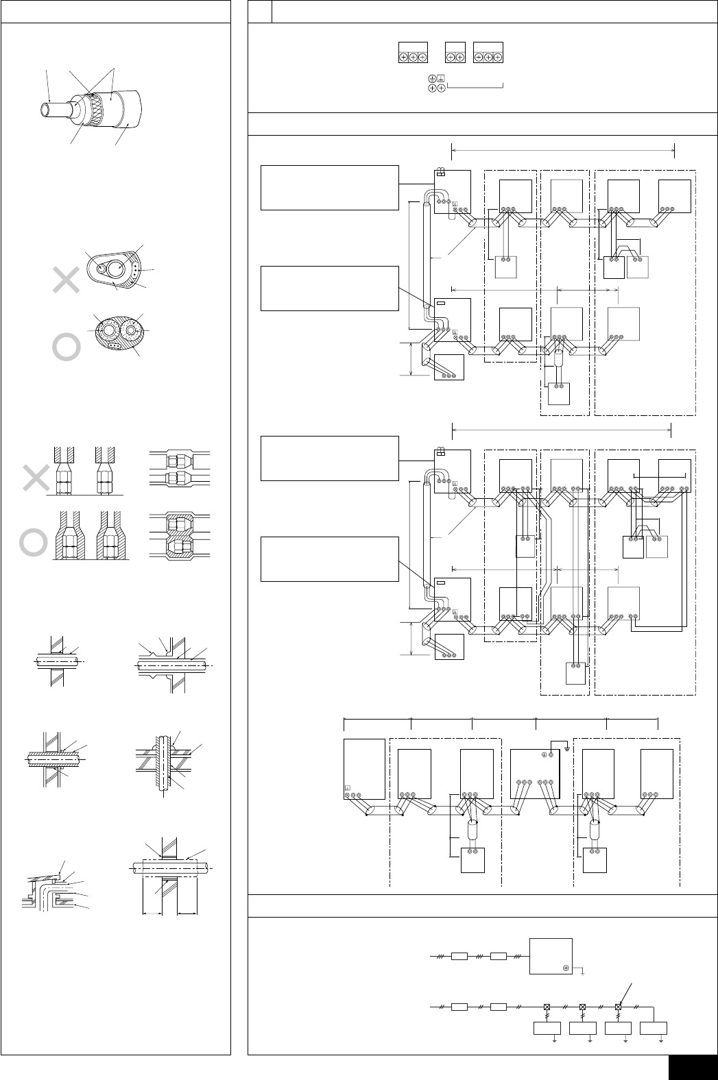
10
9.4
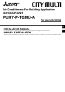
[Fig. 9.4.4]
[Fig. 9.4.3]
[Fig. 9.4.2]
C
A
B
D
E
[Fig. 9.4.1]
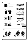
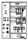
[Fig. 10.4.1]
BA
C
~208–230V
BA
~208–230V
E E
D
E E
[Fig. 10.2.1]
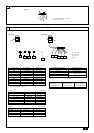
[Fig. 10.3.2]
B
A
D
C
E
E
E
D
A
B
D
F
G
B
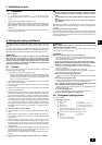
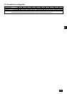
<D> Floor (waterproofing)
E
I
B
<C> Outer wall (exposed)
A B
<A> Inner wall (concealed)
A B
D
C
<B> Outer wall
F
H
D
B
G
<E> Roof pipe shaft
I
A
J
1000
[39-3/8]
1000
[39-3/8]
<F> Penetrating portion on fire
limit and boundary wall
10.3
10.2
[Fig. 10.3.1]
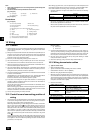
ABC
L1 L2 L3 M1M2 M1M2S
TB3 TB7
TB1
A: Steel wire B: Piping
C: Asphaltic oily mastic or asphalt
D: Heat insulation material A
E: Outer covering B
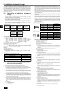
A: Liquid pipe B: Gas pipe
C: Electric wire D: Finishing tape
E: Insulator
A: Sleeve B: Heat insulating material
C: Lagging D: Caulking material
E: Band F: Waterproofing laye
G: Sleeve with edge H: Lagging material
I: Mortar or other incombustible caulking
J: Incombustible heat insulation material
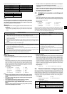
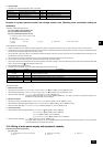
A: Power source
B: Transmission line
C: Ground screw
A: Group 1
B: Group 3
C: Group 5
D: Shielded wire
E: Sub remote
controller
( ) Address
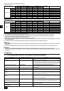
A: Switch (breakers for
wiring and current
leakage)
B: Breakers for current
leakage
C: Outdoor unit
D: Pull box
E: Indoor unit
A B C
E
D
M1 M2
M1 M2 S
TB7
TB3
IC
(51)
M1 M2 S
TB5
RC
(01)
IC
M1 M2 S
TB5
(02)
IC
M1 M2 S
TB5
(04)
IC
M1 M2 S
TB5
(03)
IC
M1 M2 S
TB5
(05)
IC
M1 M2 S
TB5
(07)
IC
M1 M2 S
TB5
(06)
L2
L1
(101)
RC
(105)
RC
(103)
RC
(155)
OC
M1 M2
M1 M2 S
TB7
TB3
CN40
(52)
OC
r3
M1M2S
System
controller
L3
L6
L4
L5
r2
r4
r1
AB AB AB
AB
CN40
A B C
E
D
M1 M2
M1 M2 S
TB7
TB3
IC
(51)
M1 M2 12S
TB5 TB15
12
TB15
12
TB15
12
TB15
12
TB15
12
TB15
MA
(01)
IC
M1 M2 S
TB5
(02)
IC
M1 M2 S
TB5
(04)
IC
M1 M2 S
TB5
(03)
IC
M1 M2 S
TB5
(05)
IC
M1 M2 S
TB5
(07)
IC
M1 M2 S
TB5
(06)
L2
L1
MA
MA
MA
OC
M1 M2
M1 M2 S
TB7
TB3
(52)
OC
c1
c4
c3
S
System
controller
L3
L6
L4
c2
AB
AB
AB
AB
M1M2
c2
c1
c1
c2
CN40
CN40
RC
N1 N2
IC
M1M2 S
TB5
IC
M1M2 S
TB5
RP
Ground
AB
ABAB
S
TB2
ABS
TB3
L4r1
M1 M2
TB3
OC
L7r1
RC
IC
M1M2 S
TB5
IC
M1M2 S
TB5
L6L5L3L2L1
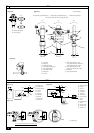
[Fig. 10.3.3]
<A> Change the jumper connec-
tor from CN41 to CN40
<B> SW2-1:ON
<C> Keep the jumper connector
on CN41
<B> SW2-1:ON
<A> Change the jumper connec-
tor from CN41 to CN40
<B> SW2-1:ON
<C> Keep the jumper connector
on CN41
<B> SW2-1:ON
(Unit : mm [in])