


13
GBDFEINLPGRRUTRCZSVSLHGPO
h. The group setting operations among the multiple indoor units is done by the remote controller (RC) after the electrical power has been turned on.
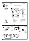
<Permissible Lengths>
1 M-NET Remote controller
• Max length via outdoor units: L
1+L2+L3+L4 and L1+L2+L3+L5 and L1+L2+L6
=
500 m [1640ft] (1.25 mm
2
[AWG16] or more)
• Max transmission cable length: L
1 and L3+L4 and L3+L5 and L6 and L2+L6
=
200 m [656ft] (1.25 mm
2
[AWG16] or more)
• Remote controller cable length:r
1, r2, r3, r4
=
10 m [32ft] (0.3 to 1.25 mm
2
[AWG22 to 16])
If the length exceeds 10 m [32ft], use a 1.25 mm
2
[AWG16] shielded wire. The length of this section (L8) should be included in the
calculation of the maximum length and overall length.
2 MA Remote controller
• Max length via outdoor unit (M-NET cable): L1+L2+L3+L4 and L1+L2+L6
=
500 m [1640ft] (1.25 mm
2
[AWG16] or more)
• Max transmission cable length (M-NET cable): L
1 and L3+L4 and L6 and L2+L6
=
200 m [656ft] (1.25 mm
2
[AWG16]
or more)
• Remote controller cable length:c
1+c2 and c1+c2+c3+c4
=
200 m [656ft] (0.3 to 1.25 mm
2
[AWG22 to 16])
3 Transmission booster
• Max transmission cable length (M-NET cable): 1 L
1+L2+L3+L5+L6
=
200 m [656ft] (1.25 mm
2
[AWG16])
2 L
1+L2+L3+L5+L7
=
200 m [656ft] (1.25 mm
2
[AWG16])
3 L
1+L2+L4
=
200 m [656ft] (1.25 mm
2
[AWG16])
4 L
6+L5+L3+L4, L4+L3+L5+L7
=
200 m [656ft] (1.25 mm
2
[AWG16])
• Remote controller cable length: r
1, r2
=
10 m [32ft] (0.3 to 1.25 mm
2
[AWG22 to 16])
If the length exceeds 10 m [32ft], use 1.25 mm
2
[AWG16] shielded cable and calculate the length of that portion (L4 and L7) as within the
total extended length and the longest remote length.
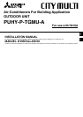
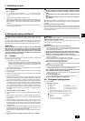
10.4. Wiring of main power supply and equipment capacity
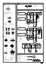
Schematic Drawing of Wiring (Example)
[Fig. 10.4.1] (P.5)
A Switch (Breakers for wiring and current leakage) B Breakers for current leakage C Outdoor unit
D Pull box E Indoor unit
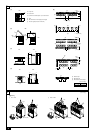
Example of a group operation system with multiple outdoor units (Shielding wires and address setting are
necessary.)
<Examples of transmission cable wiring>
[Fig. 10.3.1] M-NET Remote Controller (P.5)
[Fig. 10.3.2] MA Remote Controller (P.5)
[Fig. 10.3.3] Transmission booster unit (P.5)
<A> Change the jumper connector from CN41 to CN40
<B> SW2-1:ON
<C> Keep the jumper connector on CN41
A Group 1 B Group 3 C Group 5 D Shielded wire E Sub remote controller
( ) Address
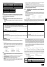
<Wiring Method and Address Settings>
a. Always use shielded wire when making connections between the outdoor unit (OC) and the indoor unit (IC), as well for all OC-OC, and IC-IC wiring intervals.
b. Use feed wiring to connect terminals M1 and M2 and the earth terminal on the transmission cable terminal block (TB3) of each outdoor unit (OC) to terminals M1, M2 and
terminal S on the transmission cable block of the indoor unit (IC).
c. Connect terminals 1 (M1) and 2 (M2) on the transmission cable terminal block of the indoor unit (IC) that has the most recent address within the same group to the
terminal block on the remote controller (RC).
d. Connect together terminals M1, M2 and terminal S on the terminal block for central control (TB7) for the outdoor unit (OC).
e. On one outdoor unit only, change the jumper connector on the control panel from CN41 to CN40.
f. Connect the terminal S on the terminal block for central control (TB7) for the outdoor unit (OC) for the unit into which the jumper connector was inserted into CN40 in Step
above to the ground terminal
in the electrical component box.
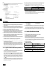
g. Set the address setting switch as follows.
* To set the outdoor unit address to 100, the outdoor address setting switch must be set to 50.
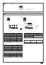
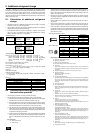
2 Wiring examples
• Controller name, symbol and allowable number of controllers.
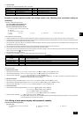
Name Code Possible unit connections
Outdoor unit
Indoor unit
Remote controller
Other
Variable capacity unit controller
Indoor unit controller
Remote controller (*1)
Transmission booster unit
–
1 to 32 units per 1 OC (*1)
2 units maximum per group
0 to 1 unit per 1 OC (*1)
OC
IC
RC
RP
*1 A transmission booster (RP) may be required depending on the number of connected indoor unit controllers.
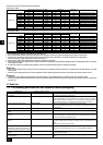
Unit Range Setting Method
IC (Main) 01 to 50 Use the most recent address within the same group of indoor units
IC (Sub) 01 to 50
Use an address, other than that of the IC (Main) from among the units within the same group of indoor units. This must be
in sequence with the IC (Main)
Outdoor Unit 51 to 100 Use the most recent address of all the indoor units plus 50
M-NET R/C (Main) 101 to 150 Set at an IC (Main) address within the same group plus 100
M-NET R/C (Sub) 151 to 200 Set at an IC (Main) address within the same group plus 150
MA R/C – Unnecessary address setting (Necessary main/sub setting)