


4
D
C
C
B
B
E
F
G
H
I
J
A
LO
HI
LO
HI
B
A
K
J
L
H
M
C
D
EN
O
F
G
I
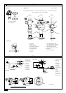
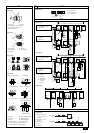
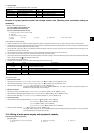
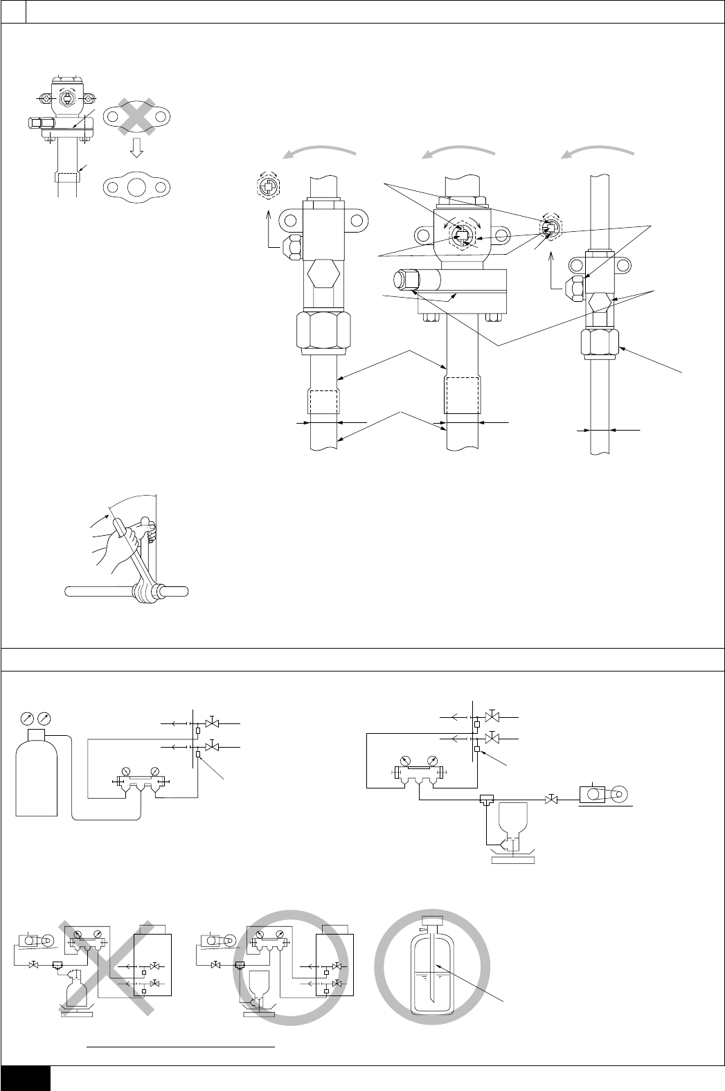
[Fig. 9.3.1]
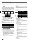
[Fig. 9.3.3]
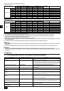
[Fig. 9.3.2]
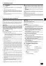
9.3
A
A: Nitrogen gas
B: To indoor unit
C: System analyzer
D: Lo knob
E: Hi knob
F: Ball valve
G: Liquid pipe
H: Gas pipe
I: Outdoor unit
J: Service port
A: System analyzer
B: Lo knob
C: Hi knob
D: Ball valve
E: Liquid pipe
F: Gas pipe
G: Service port
H: Three-way joint
I: Valve
J: Valve
K: R410A cylinder
L: Scale
M: Vacuum pump
N: To indoor unit
O: Outdoor unit
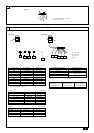
A: Syphon pipe
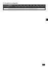
[Fig. 9.2.2]
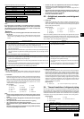
9.2
9
[Fig. 9.2.1]
A
B
1
3
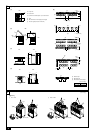
A: Valve stem
B: Stopper pin
C: Packing (Accessory)
D: Connecting pipe (Accessory)
E: Open (Operate slowly)
F: Cap, copper packing
G: Service port
H: Flare nut
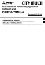
<A> [Ball valve (gas side/flanged type)]
EE
I
J
L
E
H
G
F
B
B
B
A
C
D
K
S
O
O
S
S
O
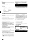
I: ø9.52 [3/8] (PUHY-P72 ~ P108)
ø12.7 [1/2] (PUHY-P126, PUHY-P144)
ø15.88 [5/8] (PUHY-P168 ~ P234)
J: ø22.2 [7/8] (PUHY-P96 ~ P108)
ø28.58 [1-1/8] (PUHY-P126 ~ P234)
K: Field piping
L: ø19.05 [3/4] (PUHY-P72)
<C> [Ball valve (gas side/flared type)]
[Fig. 9.2.3]
B In case of the cylinder having no syphon pipe.
<D> This figure shows the valve in the fully open state.
<B> [Ball valve (liquid side)]
A: Close-packed packing
B: Hollow packing
(Unit : mm [in])