


11
GBDFEINLPGRRUTRCZSVSLHGPO
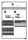
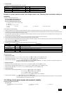
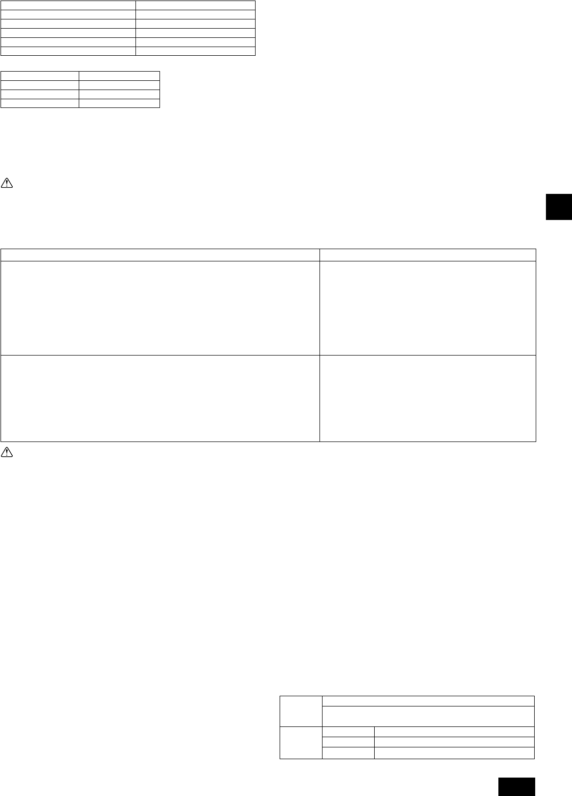
Appropriate tightening torque by torque wrench:
Copper pipe external dia. (mm [in]) Tightening torque (N·m/kg·cm)
ø6.35 [1/4] 14 to 18 / 140 to 180
ø9.52 [3/8] 35 to 42 / 350 to 420
ø12.7 [1/2] 50 to 57.5 / 500 to 575
ø15.88 [5/8] 75 to 80 / 750 to 800
ø19.05 [3/4] 100 to 140 / 1000 to 1400
Tightening angle standard:
Pipe diameter (mm [in])
Tightening angle (°)
ø6.35 [1/4], ø9.52 [3/8] 60 to 90
ø12.7 [1/2], ø15.88 [5/8]
30 to 60
ø19.05 [3/4] 20 to 35
[Fig. 9.2.3] (P.4)
Note:
If a torque wrench is not available, use the following method as a standard:
When you tighten the flare nut with a wrench, you will reach a point where
the tightening torque will abruptly increase. Turn the flare nut beyond this
point by the angle shown in the table above.
Caution:
• Always remove the connecting pipe from the ball valve and braze it out-
side the unit.
- Brazing the connecting pipe while it is installed will heat the ball valve and
cause trouble or gas leakage. The piping, etc. inside the unit may also be
burned.
• Use ester oil, ether oil or alkylbenzene (small amount) as the refrigerat-
ing machine oil to coat flares and flange connections.
- The refrigerating machine oil will degrade if it is mixed with a large amount of
mineral oil.
• Keep the ball valve closed until refrigerant charging to the pipes to be
added on site has been completed. Opening the valve before charging
the refrigerant may result in unit damage.
• Do not use a leak detection additive.
9.3. Airtight test, evacuation, and refrigerant
charging
1 Airtight test
Perform with the ball valve of the outdoor unit closed, and pressurize the con-
nection piping and the indoor unit from the service port provided on the ball
valve of the outdoor unit. (Always pressurize from both the high press pipe and
the low press pipe service ports.)
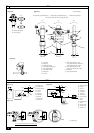
[Fig. 9.3.1] (P.4)
A Nitrogen gas B To indoor unit C System analyzer
D Lo knob E Hi knob F Ball valve
G Liquid pipe H Gas pipe I Outdoor unit
J Service port
Observe the following restrictions when conducting an air tightness test to prevent
negative effects on the refrigerating machine oil. Also, with nonazeotropic refriger-
ant (R410A), gas leakage causes the composition to change and affects perform-
ance. Therefore, perform the airtightness test cautiously.
Caution:
Only use refrigerant R410A.
- The use of other refrigerant such as R22 or R407C, which contains chlorine, will
deteriorate the refrigerating machine oil or cause the compressor to malfunction.
2 Evacuation
Evacuate with the ball valve of the outdoor unit closed and evacuate both the
connection piping and the indoor unit from the service port provided on the ball
valve of the outdoor unit using a vacuum pump. (Always evacuate from the
service port of both liquid pipe and gas pipe.) After the vacuum reaches 650
Pa [abs] [0.0943 psi/5Torr], continue evacuation for at least one hour or more.
* Never perform air purging using refrigerant.
[Fig. 9.3.2] (P.4)
A System analyzer B Lo knob C Hi knob
D Ball valve E Liquid pipe F Gas pipe
G Service port H Three-way joint I Valve
J Valve K R410A cylinder L Scale
M Vacuum pump N To indoor unit O Outdoor unit
Note:
• Always add an appropriate amount of refrigerant. Also always seal the
system with liquid refrigerant. Too much or too little refrigerant will cause
trouble.
• Use a gauge manifold, charging hose, and other parts for the refrigerant
indicated on the unit.
• Use a gravimeter. (One that can measure down to 0.1 kg [3oz].)
• Use a vacuum pump with a reverse flow check valve.
(Recommended vacuum gauge: ROBINAIR 14830A Thermistor Vacuum
Gauge)
Also use a vacuum gauge that reaches 65 Pa [abs] [0.00943 psi/0.5Torr]
or below after operating for five minutes.
3 Refrigerant Charging
Since the refrigerant used with the unit is nonazerotropic, it must be charged in
the liquid state. Consequently, when charging the unit with refrigerant from a
cylinder, if the cylinder does not have a syphon pipe, charge the liquid refriger-
ant by turning the cylinder upside-down as shown in Fig.9.3.3. If the cylinder
has a syphon pipe like that shown in the picture on the right, the liquid refriger-
ant can be charged with the cylinder standing upright. Therefore, give careful
attention to the cylinder specifications. If the unit should be charged with gas
refrigerant, replace all the refrigerant with new refrigerant. Do not use the re-
frigerant remaining in the cylinder.
[Fig. 9.3.3] (P.4)
A Syphon pipe B In case of the cylinder having no syphon pipe.
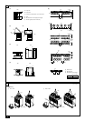
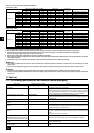
9.4. Thermal insulation of refrigerant piping
Be sure to give insulation work to refrigerant piping by covering liquid pipe and gas
pipe separately with enough thickness heat-resistant polyethylene, so that no gap
is observed in the joint between indoor unit and insulating material, and insulating
materials themselves. When insulation work is insufficient, there is a possibility of
condensation drip, etc. Pay special attention to insulation work to ceiling plenum.
[Fig. 9.4.1] (P.5)
A Steel wire B Piping
C Asphaltic oily mastic or asphalt D Heat insulation material A
E Outer covering B
Glass fiber + Steel wire
Adhesive + Heat - resistant polyethylene foam + Adhesive tape
Indoor Vinyl tape
Floor exposed Water-proof hemp cloth + Bronze asphalt
Outdoor Water-proof hemp cloth + Zinc plate + Oily paint
Restriction
• If a flammable gas or air (oxygen) is used as the pressurization
gas, it may catch fire or explode.
• Do not use a refrigerant other than that indicated on the unit.
• Sealing with gas from a cylinder will cause the composition of
the refrigerant in the cylinder to change.
• Use a pressure gauge, charging hose, and other parts especially
for R410A.
• An electric leak detector for R22 cannot detect leaks of R410A.
• Do not use a haloid torch. (Leaks cannot be detected.)
Airtight test procedure
1. Nitrogen gas pressurization
(1) After pressurizing to the design pressure (4.15 MPa [602psi]) using nitrogen gas, allow it to
stand for about one day. If the pressure does not drop, airtightness is good.
However, if the pressure drops, since the leaking point is unknown, the following bubble test
may also be performed.
(2) After the pressurization described above, spray the flare connection parts, brazed parts, flanges,
and other parts that may leak with a bubbling agent (Kyuboflex, etc.) and visually check for
bubbles.
(3) After the airtight test, wipe off the bubbling agent.
2. Pressurization using refrigerant gas and nitrogen gas
(1) Pressurizing to a gas pressure of approximately 0.2 MPa [29psi], pressurize to the design
pressure (4.15 MPa [602psi]) using nitrogen gas.
However, do not pressurize at one time. Stop during pressurization and check that the pres-
sure does not drop.
(2) Check for gas leaks by checking the flare connection parts, brazed parts, flanges, and other
parts which may leak using an R410A compatible electric leak detector.
(3) This test may be used together the with bubble type gas leak test.
Heat
insulation
material A
Outer
covering B