


14
GBDFEINLPGRRUTRCZSVSLHGPO
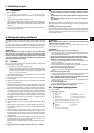
11. Test run
Warning:
• Be sure to use specified wires to connect so that no external force is imparted to terminal connections. If connections are not fixed firmly, it may cause
heating or fire.
• Be sure to use the appropriate type of overcurrent protection switch. Note that generated overcurrent may include some amount of direct current.
Caution:
• A breaker for current leakage must be attached to the power supply. If no earth leakage breaker is installed, it may cause an electric shock.
• Do not use anything other than breaker and fuse with correct capacity. Using fuse and wire or copper wire with too large capacity may cause a malfunction
of unit or fire.
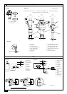
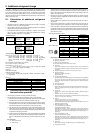
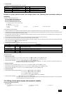
11.1. The following phenomena do not represent trouble (emergency)
Display of remote controller
“Cooling (heating)” flashes
Normal display
Normal display
Defrost display
No lighting
Heat ready
Normal display
“HO” or “PLEASE WAIT” flashes
Light out
Cause
When another indoor unit is performing the heating (cooling) operation, the cool-
ing (heating) operation is not performed.
Because of the control operation of auto vane, it may change over to horizontal
blow automatically from the downward blow in cooling in case the downward
blow operation has been continued for 1 hour. At defrosting in heating, hot adjust-
ing and thermostat OFF, it automatically changes over to horizontal blow.
Ultra-low speed operation is commenced at thermostat OFF.
Light air automatically changes over to set value by time or piping temperature at
thermostat ON.
The fan is to stop during defrosting.
Fan is to run for 1 minute after stopping to exhaust residual heat (only in heating).
Ultra low-speed operation for 5 minutes after SW ON or until piping temperature
becomes 35°C [95°F], low speed operation for 2 minutes thereafter, and then set
notch is commenced. (Hot adjust control)
When the outdoor unit is being cooled and the refrigerant is resting, warming up
operation is performed for at least 30 minutes to warm the compressor (only
P72).
During this time, only the fan operates.
System is being driven.
Operate remote controller again after “HO” or “PLEASE WAIT” disappear.
After a stop of cooling operation, unit continues to operate drain pump for three
minutes and then stops it.
Unit continues to operate drain pump if drainage is generated, even during a
stop.
Phenomenon
Indoor unit does not the perform cooling (heat-
ing) operation.
The auto vane runs freely.
Fan setting changes during heating.
Fan stops during heating operation.
Fan does not stop while operation has been
stopped.
No setting of fan while start SW has been
turned on.
Outdoor unit does not operate by turning
switch on.
Indoor unit remote controller shows “HO” or
“PLEASE WAIT” indicator for about five min-
utes when turning ON universal power supply.
Drain pump does not stop while unit has been
stopped.
Drain pump continues to operate while unit
has been stopped.
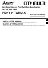
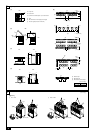
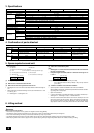
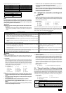
1. Use a separate power supply for the outdoor unit and indoor unit.
2. Bear in mind ambient conditions (ambient temperature, direct sunlight, rain water, etc.) when proceeding with the wiring and connections.
3. The wire size is the minimum value for metal conduit wiring. The power cord size should be 1 rank thicker consideration of voltage drops.
Make sure the power-supply voltage does not drop more than 10 %.
4. Specific wiring requirements should adhere to the wiring regulations of the region.
5. Power supply cords of parts of appliances for outdoor use shall not be lighter than polychloroprene sheathed flexible cord (design 245 IEC57). For example,
use wiring such as YZW.
6. A switch with at least 3 mm [1/8in] contact separation in each pole shall be provided by the Air conditioner installation.
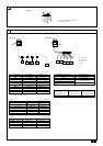
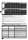
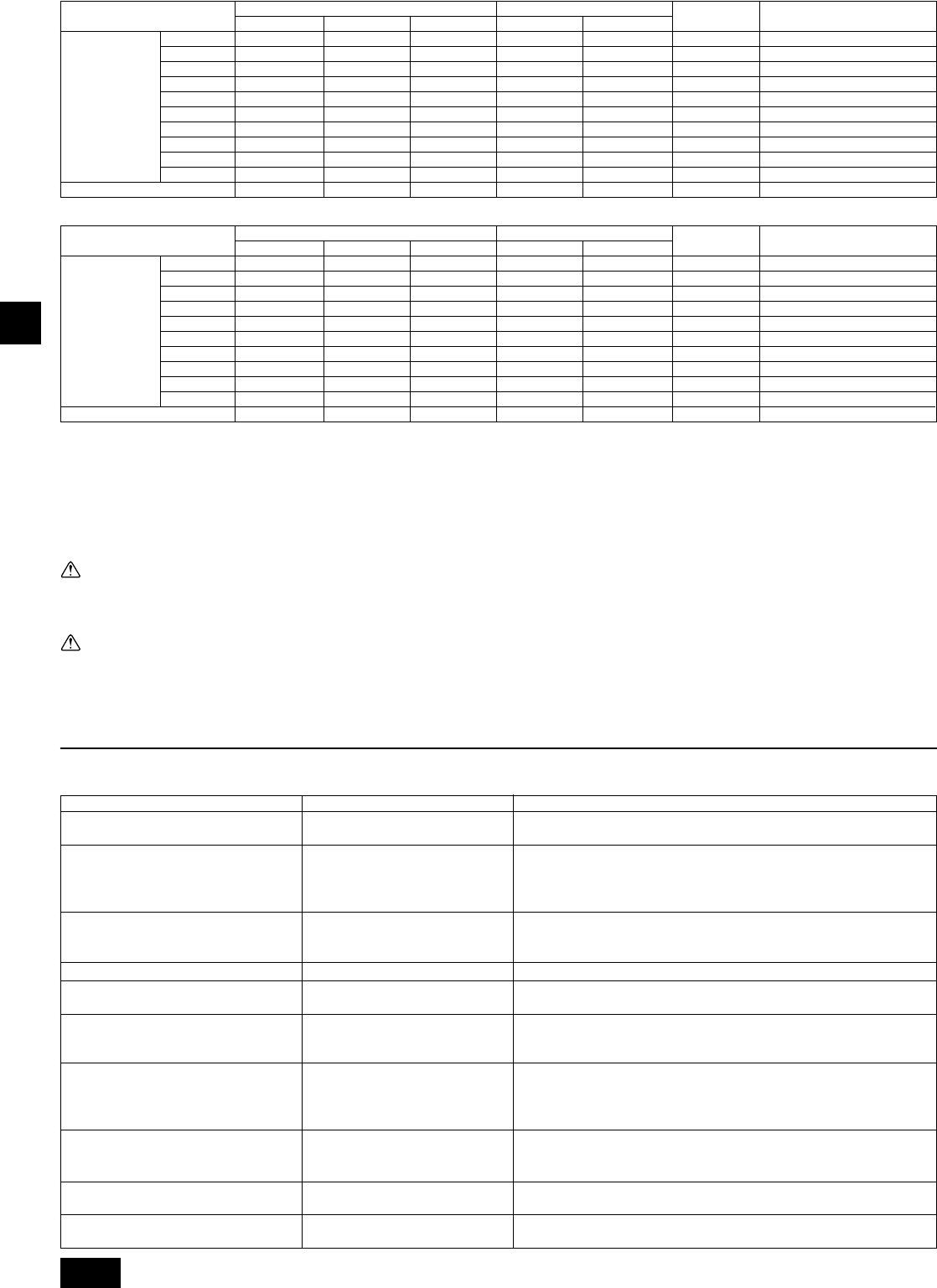
Thickness of wire for main power supply, On/Off capacities
<Power soure : 208 V>
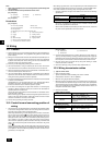
<Power soure : 230 V>
40
50
50
60
75
75
100
100
100
125
20
40
50
50
60
75
75
100
100
100
125
16
40
50
50
60
75
75
100
100
100
125
16
8.4/8
13.3/6
13.3/6
21.2/4
33.6/2
33.6/2
42.4/1
42.4/1
42.4/1
53.5/1/0
1.5
8.4/8
13.3/6
13.3/6
21.2/4
33.6/2
33.6/2
42.4/1
42.4/1
42.4/1
53.5/1/0
1.5
Main cable
Switch (A)
Minimum wire thickness (mm
2
/AWG)
Branch Capacity Fuse
Outdoor unit
P72
P96
P108
P126
P144
P168
P192
P204
P216
P234
–
–
–
–
–
–
–
–
–
–
1.5
Breaker for
wiring (NFB)Ground
40 A 100 mA 0.1 sec. or less
50 A 100 mA 0.1 sec. or less
50 A 100 mA 0.1 sec. or less
60 A 100 mA 0.1 sec. or less
75 A 100 mA 0.1 sec. or less
75 A 100 mA 0.1 sec. or less
100 A 100 mA 0.1 sec. or less
100 A 100 mA 0.1 sec. or less
100 A 100 mA 0.1 sec. or less
125 A 100 mA 0.1 sec. or less
20 A 30 mA 0.1 sec. or less
Breaker for current leakage
Indoor unit
40
50
50
60
75
75
100
100
100
100
15
40
50
50
60
75
75
100
100
100
100
15
40
50
50
60
75
75
100
100
100
100
15
8.4/8
13.3/6
13.3/6
21.2/4
33.6/2
33.6/2
42.4/1
42.4/1
42.4/1
42.4/1
0.41/22
8.4/8
13.3/6
13.3/6
21.2/4
33.6/2
33.6/2
42.4/1
42.4/1
42.4/1
42.4/1
0.41/22
Main cable
Switch (A)
Minimum wire thickness (mm
2
/AWG)
Branch Capacity Fuse
Outdoor unit
P72
P96
P108
P126
P144
P168
P192
P204
P216
P234
–
–
–
–
–
–
–
–
–
–
0.41/22
Breaker for
wiring (NFB)Ground
40 A 100 mA 0.1 sec. or less
50 A 100 mA 0.1 sec. or less
50 A 100 mA 0.1 sec. or less
60 A 100 mA 0.1 sec. or less
75 A 100 mA 0.1 sec. or less
75 A 100 mA 0.1 sec. or less
100 A 100 mA 0.1 sec. or less
100 A 100 mA 0.1 sec. or less
100 A 100 mA 0.1 sec. or less
100 A 100 mA 0.1 sec. or less
20 A 30 mA 0.1 sec. or less
Breaker for current leakage
Indoor unit