


12
GBDFEINLPGRRUTRCZSVSLHGPO
Note:
• When using polyethylene cover as covering material, asphalt roofing shall
not be required.
• No heat insulation must be provided for electric wires.
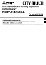
[Fig. 9.4.2] (P.5)
A Liquid pipe B Gas pipe C Electric wire
D Finishing tape E Insulator
[Fig. 9.4.3] (P.5)
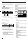
Penetrations
[Fig. 9.4.4] (P.5)
<A> Inner wall (concealed) <B> Outer wall
<C> Outer wall (exposed) <D> Floor (waterproofing)
<E> Roof pipe shaft
<F> Penetrating portion on fire limit and boundary wall
A Sleeve B Heat insulating material
C Lagging D Caulking material
E Band F Waterproofing laye
G Sleeve with edge H Lagging material
I Mortar or other incombustible caulking
J Incombustible heat insulation material
10. Wiring
10.1. Caution
1 Follow ordinance of your governmental organization for technical standard re-
lated to electrical equipment, wiring regulations and guidance of each electric
power company.
2 Wiring for control (hereinafter referred to as transmission line) shall be (5 cm or
more [2in or more]) apart from power source wiring so that it is not influenced
by electric noise from power source wiring. (Do not insert transmission line
and power source wire in the same conduit.)
3 Be sure to provide designated grounding work to outdoor unit.
4 Give some allowance to wiring for electrical part box of indoor and outdoor
units, because the box is sometimes removed at the time of service work.
5 Never connect the main power source to terminal block of transmission line. If
connected, electrical parts will be burnt out.
6 Use 2-core shield cable for transmission line. If transmission lines of different
systems are wired with the same multiplecore cable, the resultant poor trans-
mitting and receiving will cause erroneous operations.
7 Only the transmission line specified should be connected to the terminal block
for outdoor unit transmission.
(Transmission line to be connected with indoor unit : Terminal block TB3 for
transmission line, Other : Terminal block TB7 for centralized control)
Erroneous connection does not allow the system to operate.
8 In the case of connecting with an upper class controller or to conduct group
operation in different refrigerant systems, the control line for transmission is
required between the outdoor units.
Connect this control line between the terminal blocks for centralized control.
(2-wire line with no polarity)
When conducting group operation in different refrigerant systems without con-
necting to the upper class controller, replace the insertion of the short circuit
connector from CN41 of one outdoor unit to CN40.
9 Group is set by operating the remote controller.
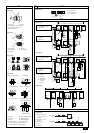
10.2. Control box and connecting position of
wiring
1. Connect the indoor unit transmission line to transmission terminal block (TB3),
or connect the wiring between outdoor units or the wiring with the central con-
trol system to the central control terminal block (TB7).
When using shielded wiring, connect shield ground of the indoor unit transmis-
sion line to the ground screw (
) and connect shield ground of the line be-
tween outdoor units and the central control system transmission line to the
shield (S) terminal of the central control terminal block (TB7) shield (S) termi-
nal. In addition, in the case of outdoor units whose power supply connector
CN41 has been replaced by CN40, the shield terminal (S) of terminal block
(TB7) of the central control system should also be connected to the ground
screw (
).
Fix the wiring securely in place with the cable strap at the bottom of the termi-
nal block so that the external force if not applied to the terminal block. External
force applied to the terminal block may damage the block and short-circuit,
ground fault, or fire may result.
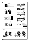
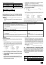
[Fig. 10.2.1] (P.5)
A Power source B Transmission line
C Ground screw
2. Conduit mounting plates (ø27 mm [1-3/32 in], ø33 mm [1-5/16 in], ø46 mm [1-
13/16 in], ø53 mm [2-3/32 in]) are being provided. Pass the power supply and
transmission wires through the appropriate knock-out holes, then remove the
knock-out piece from the bottom of the terminal box and connect the wires.
3. Fix power source wiring to terminal box by using buffer bushing for tensile
force (PG connection or the like).
4. Narrow the opening by using a conduit to keep small animals out.
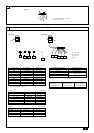
10.3. Wiring transmission cables
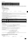
1 Types of control cables
1. Wiring transmission cables
• Types of transmission cables: Shielding wire CVVS or CPEVS
• Cable diameter: More than 1.25 mm
2
[AWG16]
• Maximum wiring length: Within 200 m [655ft]
• Maximum length of transmission lines for centralized control and indoor/out-
door transmission lines (Maximum length via indoor units): 500 m [1640ft] MAX
The maximum length of the wiring between power supply unit for transmission
lines (on the transmission lines for centralized control) and each outdoor unit
and system controller is 200 m [655ft].
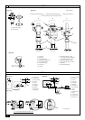
2. Remote control cables
• M-NET Remote Controller
When filling a gap with mortar, cover the penetration part with steel plate so that
the insulation material will not be caved in. For this part, use incombustible materi-
als for both insulation and covering. (Vinyl covering should not be used.)
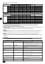
• Insulation materials for the pipes to be added on site must meet the following
specifications:
Kind of remote control cable
Cable diameter
Remarks
Sheathed 2-core cable (unshielded) CVV
0.3 to 1.25 mm
2
[AWG22 to 16]
(0.75 to 1.25 mm
2
[AWG18 to 16])*
Within 200 m [656ft]
• MA Remote Controller
* Connected with simple remote controller.
* Installation of pipes in a high-temperature high-humidity environment, such as
the top floor of a building, may require the use of insulation materials thicker
than the ones specified in the chart above.
* When certain specifications presented by the client must be met, ensure that
they also meet the specifications on the chart above.
Thickness
Temperature Resistance
Pipe size
ø6.35 to 25.4 mm [1/4 to 1 in]
10 mm min. [13/32 in min]
ø28.58 to 38.1 mm [1-1/8 to 1-1/2 in]
15 mm min. [19/32 in min]
100 °C min.
Kind of remote control cable
Cable diameter
Remarks
Sheathed 2-core cable (unshielded)
0.3 to 1.25 mm
2
[AWG22 to 16]
(0.75 to 1.25 mm
2
[AWG18 to 16])*
When 10 m [32ft] is exceeded, use cable with
the same specifications as 1. Wiring transmis-
sion cables.