


6G7 ENGINE (E-W) -
Piston and Connecting Rod
11A-12-6
"
D
A
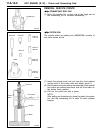
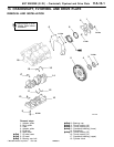
PISTON AND CONNECTING ROD
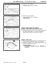
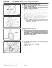
(1) Liberally coat the circumference of the piston, piston ring,
and oil ring with engine oil.
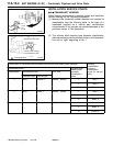
(2) Arrange the piston ring and oil ring gaps (side rail and
spacer) as shown in the figure.
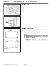
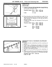
(3) Rotate the crankshaft so that the crank pin is positioned
at the centre line of the cylinder bore.
(4) Use suitable thread protectors on connecting rod bolts
before inserting piston and connecting rod assembly into
cylinder block.
Care must be taken not to nick crank pin.
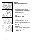
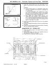
(5) Using a suitable piston ring compressor tool, install piston
and connecting rod assembly into cylinder block.
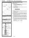
Caution
D
Install the piston with the front mark (arrow mark)
on the top of the piston facing towards the engine
front (timing belt side).
"
E
A
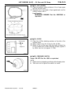
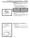
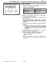
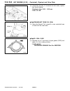
CONNECTING ROD CAP
(1) Mate the correct bearing cap with the correct connecting
rod by checking with th e alignment marks marked during
disassembly. If a new connecting rod is used which has
no alignment mark, position the notches for locking the
bearing on the same side.
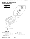
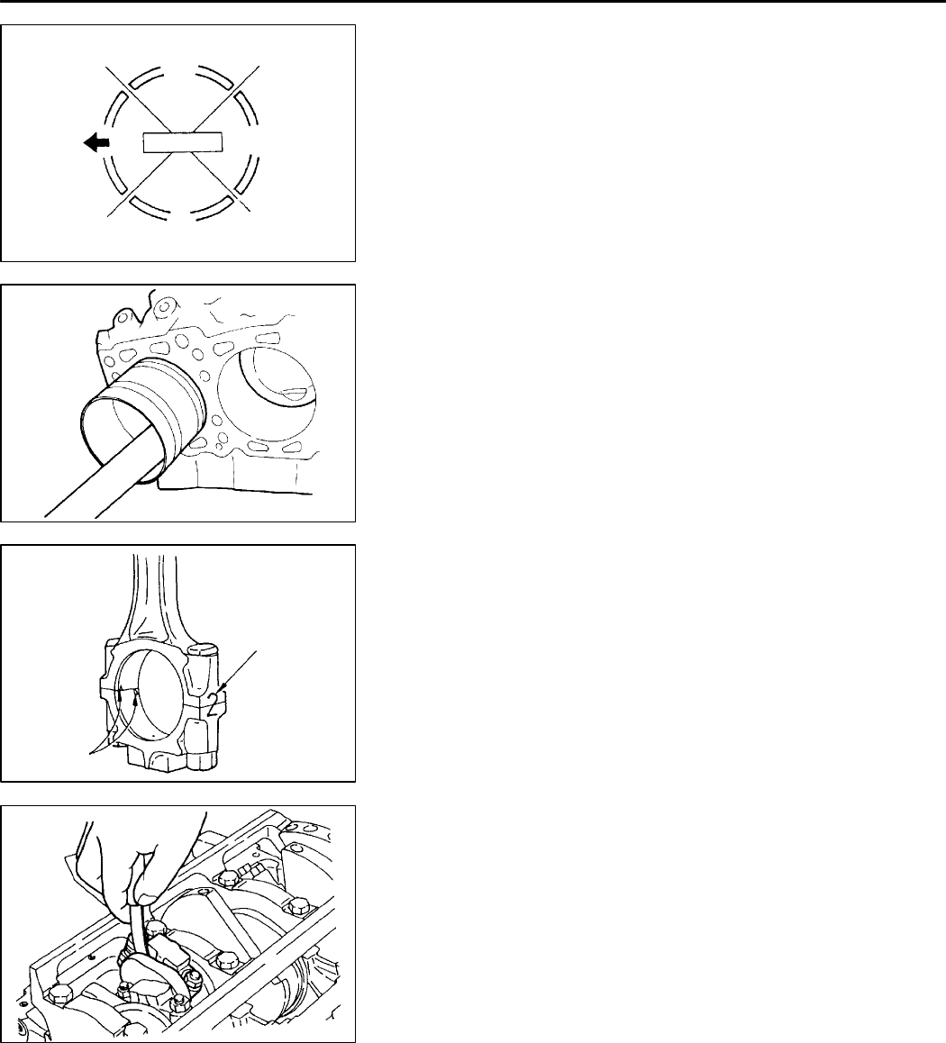
(2) Check if the thrust clearance in the connecting rod big
end is correct.
Standard value: 0.10 - 0.25 mm
Limit: 0.4 mm
PWEE9615
E
Dec. 1996Mitsubishi Motors Corporation
6EN0549
Upper side rail
No. 2 ring gap
and spacer gap
Lower side rail
No. 1
Piston pin
7EN0032
7EN0453
Cylinder
number
Notches
7EN0454