


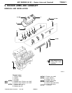
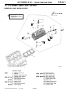

6G7 ENGINE (E-W) -
Cylinder Head and Valves
11A-10-5
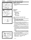
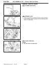
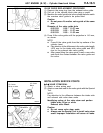
VALVE GUIDE REPLACEMENT PROCEDURE
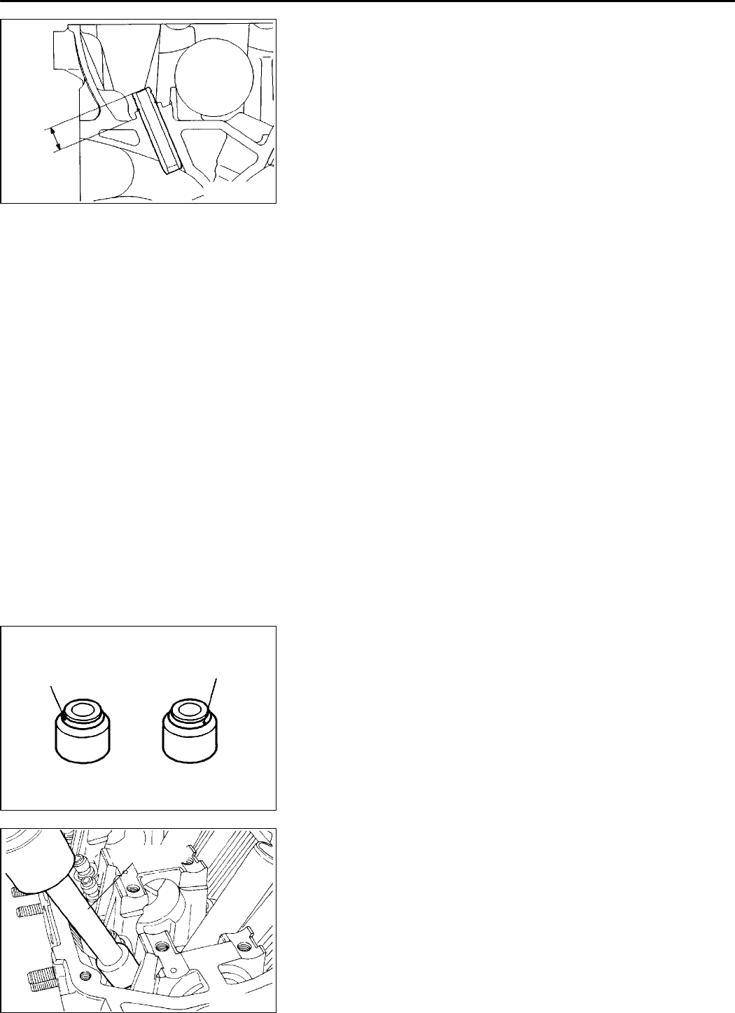
(1) Remove the snap ring from the exhaust valve guide.
(2) Pull out to the cylinder block side using a press.
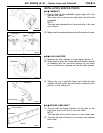
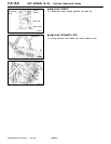
(3) Machine the valve guide hole in the cylinder head to match
the oversize valve guide to be press fitted.
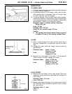
Caution
D
Do not press fit another valve guide of the same
size.
Diameter of the valve guide hole
0.05 O.S. 11.05 - 11.07 mm
0.25 O.S. 11.25 - 11.27 mm
0.50 O.S. 11.50 - 11.52 mm
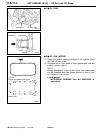
(4) Press fit the valve guide until the projection is 14.0 mm,
as shown.
NOTE
D Press fit the valve guide from the top surface of the
cylinder head.
D Pay attention to the difference inthe valve guidelength
(45.5 mm for the intake side valve guide and 50.5
mm for the exhaust side valve guide).
D After press fitting the valve guide, insert a new valve
and check the contact between the valve guide and
the valve.
INSTALLATION SERVICE POINTS
"
A
A
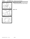
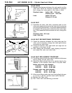
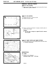
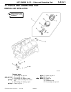
VALVE STEM SEAL
(1) Attach a valve spring seat.
(2) Attach a new stem seal to the valve guide with the Special
Tool.
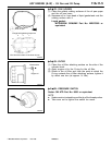
NOTE
Pay attention to the difference between the intake side
and exhaust side valve stem seals.
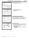
Identifying colour at the valve stem seal portion
Intake side: Silver or white
Exhaust side: Black
Caution
D
Do not reuse valve stem seals.
D
Always use the Special Tool to install valve stem
seals. Improper installation will cause oil leaks.
PWEE9615
E
Dec. 1996Mitsubishi Motors Corporation
7EN0726
14.0 mm
7EN0763
I.D. Colour
Silver or white
Intake side Exhaust side
I.D. Colour
Black
6AE0169
MD998774