


6G7 ENGINE (E-W) -
Cylinder Head and Valves
11A-10-4
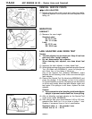
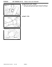
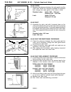
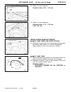
VALVE GUIDE
(1) Measure the clearance between the valve guide and the
valve stem. When the clearance exceeds the specified
limit, change the valve guide or the valve or both.
Standard value: Intake 0.02 - 0.04 mm
Exhaust 0.04 - 0.06 mm
Limit: Intake 0.10 mm
Exhaust 0.15 mm
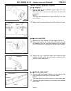
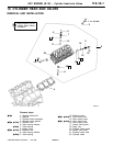
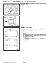
VALVE SEAT
(1) Assemble the valve, and with it pressed down on the
valve seat measure the part of the valve which protrudes
from the spring seat surface. The length measured should
be between the spring seat surface and the valve stem
end. If the measured value exceeds the limit, change the
valve.
Standard value: 49.3 mm
Limit: 49.8 mm
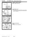
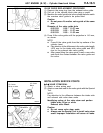
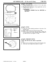
VALVE SEAT RECONDITIONING PROCEDURE
(1) Check the clearance between the valve guide and the
valve, and if necessary, change the valve guide before
correcting the valve seat.
(2) Correct so that the valve seat width and angle are as
specified in the figure at left.
(3) After making the corrections, apply lapping compound
and adjust the valve and valve seat.
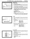
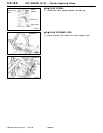
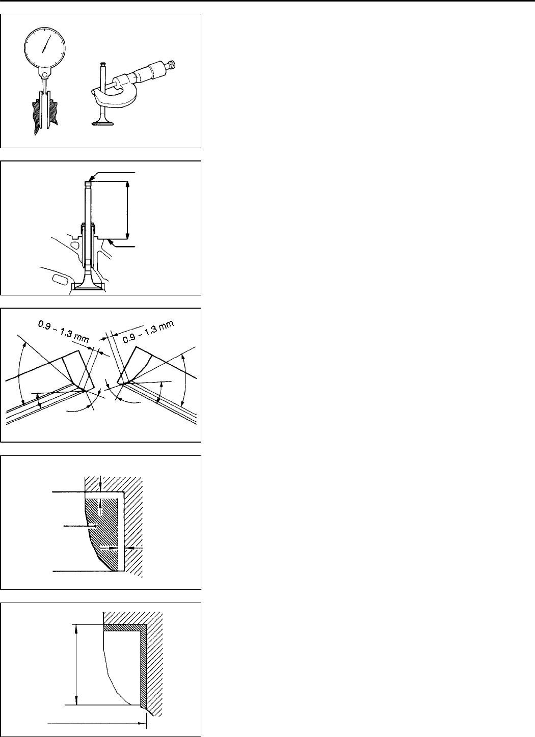
VALVE SEAT REPLACEMENT PROCEDURE
(1) Cut off the inside of the valve seat to reduce its thickness
before pulling out the valve seat.
(2) Adjust the valve cylinder hole in the cylinder head to the
diameter of the oversize valve seat to be press fitted.
Intake valve seat hole diameter
0.30 O.S. 34.30 - 34.33 mm
0.60 O.S. 34.60 - 34.63 mm
Exhaust valve seat hole diameter
0.30 O.S. 31.80 - 31.83 mm
0.60 O.S. 32.10 - 32.13 mm
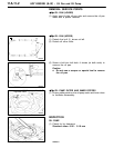
(3) When press fitting a valve seat, cool it using liquid nitrogen
so as not to gall the cylinder head inside diameter.
(4) Machine the valve seat.
(5) See “Valve seat reconditioning procedure.”
PWEE9615
E
Dec. 1996Mitsubishi Motors Corporation
1EN0279
Stem outside diameter
Guide inside diameter
DEN0212
Valve stem
end
Valve
protrusion
Spring seat
surface
7EN0273
65
_
15
_
44
_
44
_
65
_
25
_
1EN0274
Cut off
0.5 - 1 mm
0.5 - 1 mm
1EN0275
Height of
valve seat
Oversize hole diameter