


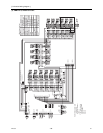
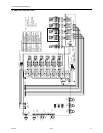
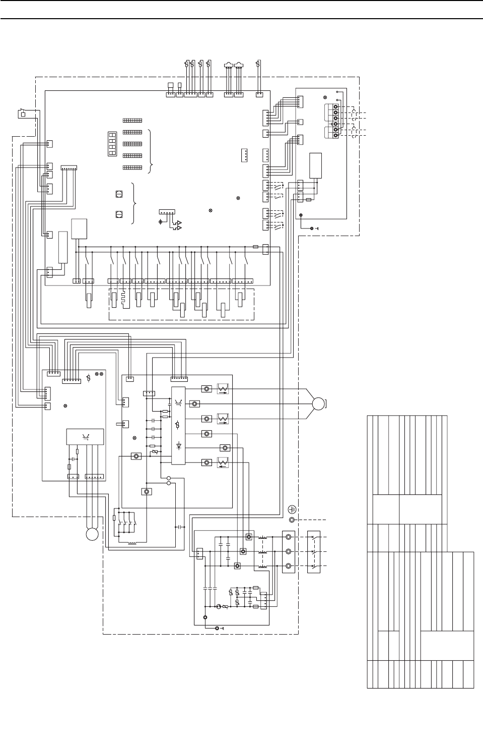
[ V Electrical Wiring Diagram ]
- 93 -
HWE0803A GB
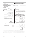
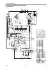
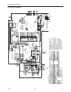
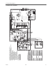
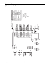
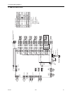
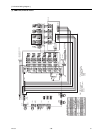
V Electrical Wiring Diagram
[1] Electrical Wiring Diagram of the Outdoor Unit
(1) PURY-P72THMU-A
L
G
Ground
G
Heat exchanger low pressure
bypass
SV5c
Explanation
Symbol
1
SV5b
X05
3
6
CN506
6
L3
L2
L1
1
*1.Single-dotted lines indicate wiring
not supplied with the unit.
*2.Dot-dash lines indicate the control
box boundaries.
*3.Refer to the Data book for connecting
input/output signal connectors.
*4.Daisy-chain terminals (TB3) on the
outdoor units in the same refrigerant
system together.
*5.Faston terminals have a locking
function.Make sure the terminals
are securely locked in place after
insertion.Press the tab on the
terminals to removed them.
SV1a
CN504
green
3
1
CH11
3
1
X03
CN503
blue
72C
2
1
X02
CN502
SV5b
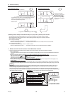
<Symbol explanation>
DCL
SV1a
SV4a,b,d
CT12,22,3
CN02
Motor
(Compressor)
TB21
F2
AC250V
6.3A T
CH11
CN5V
yellow
CN22
red
31
Fan motor
(Heat exchanger)
U
21
CNT01
V
M
3~
21
CN18V
blue
CNDC
pink
CN4
12 45
1
2
3
4
CN21
blue
1
2
3
4
5
CPU power
supply circuit
72C
1
F01
AC250V
3.15A T
CN03
black
1313
6
2
M-NET power
supply
circuit
12
2
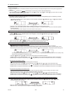
M-NET Board
63LS
*4
7
4
63HS1
TH4
63H1
Symbol
21S4a
SV2
THBOX
Z24,25
THHS
TH7
TH6
TH5
TH4
TH3
TB7
TB3
TB1
SV9
3
2
1
Indoor/Outdoor
transmission
cable
Central control
transmission
cable
63HS1
5
red
CNAC
63LS
3
TP2
2
CN2
1
Control Board
DC reactor
Solenoid
valve
Crankcase heater(for heating the compressor)
Current sensor(AC)
Magnetic relay(inverter main circuit)
Low pressure
Discharge pressure
High pressure protection for the
outdoor unit
Pressure
switch
Pressure
sensor
Explanation
3
4-way valve(Cooling/Heating switching)
TH5
For opening/closing the bypass
circuit under the O/S
TP1
TH6
TH7
Discharge suction bypass
Heat exchanger capacity control
For opening/closing the bypass
circuit
Control box internal temperature
Liquid pipe temperature
TH3
Thermistor
Discharge pipe temperature
TB3
M1 M2 M1M2 S
TB7
123
6
4512
1234
ACC inlet pipe temperature
OA temperature
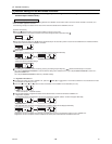
2
FAN Board
LED1
Unit address setting
LED1:Power supply to
Indoor/Outdoor
transmission line
CN102
CNS2
yellow
SWU2
10's digit
SWU1
1's digit
10
1
10
1
10
1
10
1
SW4 SW3 SW2 SW1
ON
IGBT temperature
Function setting connector
Power supply
Indoor/Outdoor transmission
cable
Central control transmission
cable
OFF ON OFF ON
Terminal
block
Heat exchanger inlet pipe
temperature
For opening/closing the bypass
circuit
OFF ON
X04
*3
LED3:Lit when powered
CN01
red
5
black
3
CNINV
1
3
CNVDC
CNIT
red
F01
AC250V
15A T
1
1
R630
3
1
2
C630
IPM
2
1
LED3:CPU in
operation
1
t°
LED1:Normal
operation
2
1
1
OFF
2323123
blue
CN3N
yellow
CN3K
F01
AC250V
3.15A T
4521
OFF
432112 431
21
X10
X08
122131
CN801
yellow
CNT02
CN332
blue
CN4
X09
CN508
black
1
5
3
6
2
1
2
2
3
3123
CN41CN102CN3D
4
1
red
CN3S
red
CNIT
yellow
CNS2
CN202
red
CN201
CN211
4321
Power selecting
connector
2
1
Z24
Z25
3
SV9
SV2
ON
CNTYP5
green
CNTYP4
green
CN990
CN40
LED2:CPU in operation
CN212
CN213
red
TB1
L3L2
whitered
Noise Filter
F1
AC250V
6.3A T
CX6
CY3
V
black
SC-V
7
black
INV Board
RSH2
3
ZNR1
C32
red
black
CN6
SC-U
CN2
SC-T
MS
3~
*5
CX5
C1
U
CN4
black
red
white
U
72C
31
R30
TB23
TB22
1
CT22
DSA1
black
1
CX2
CY1
CX1
Z3
CX3
Z4
Z1
U
SC-P2
3
CY2
CX4
black
white
*5
red
red
CT12
black
SC-W
1
SC-S
red
CT3
SC-R
red
R1
DCL
2
5
C31
C1
RSH1
U
C30
IGBT
CNDC
pink
LED1:Normal operation(Lit)
/Error(Blink)
2
1
2
THHS
1
TB-P
44
3334
*5
1314
23
43
24
white
red
white
21S4a
+++
TB-N
SC-P1
1
P
63H1
Power supply
3~
60Hz
208/230V
CN04
red
LED2:Error
THBOX
U
Z2
U
ONOFF
1
10
SW5
12V
5
4
3
1
CN51
*3
Function setting
LED1
Display
setting
Compressor ON/OFF output
Error detection output
L1
+
CN510
yellow
6
3
X13
1
SV5c
X12
1
5
SV4b
X07
CN507
red
1
5
3
6
SV4d
SV4a
white
CNAC2
black
1
3
2
1
X72
CN505
black
A1
A2
CN509
blue
Power
failure
detection
circuit
t°
t°
t°
t°
t°
t°
W
W