


OC277-54
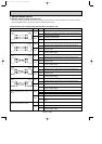
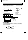
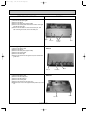
6. MULTIPLE REMOTE CONTROL DISPLAY
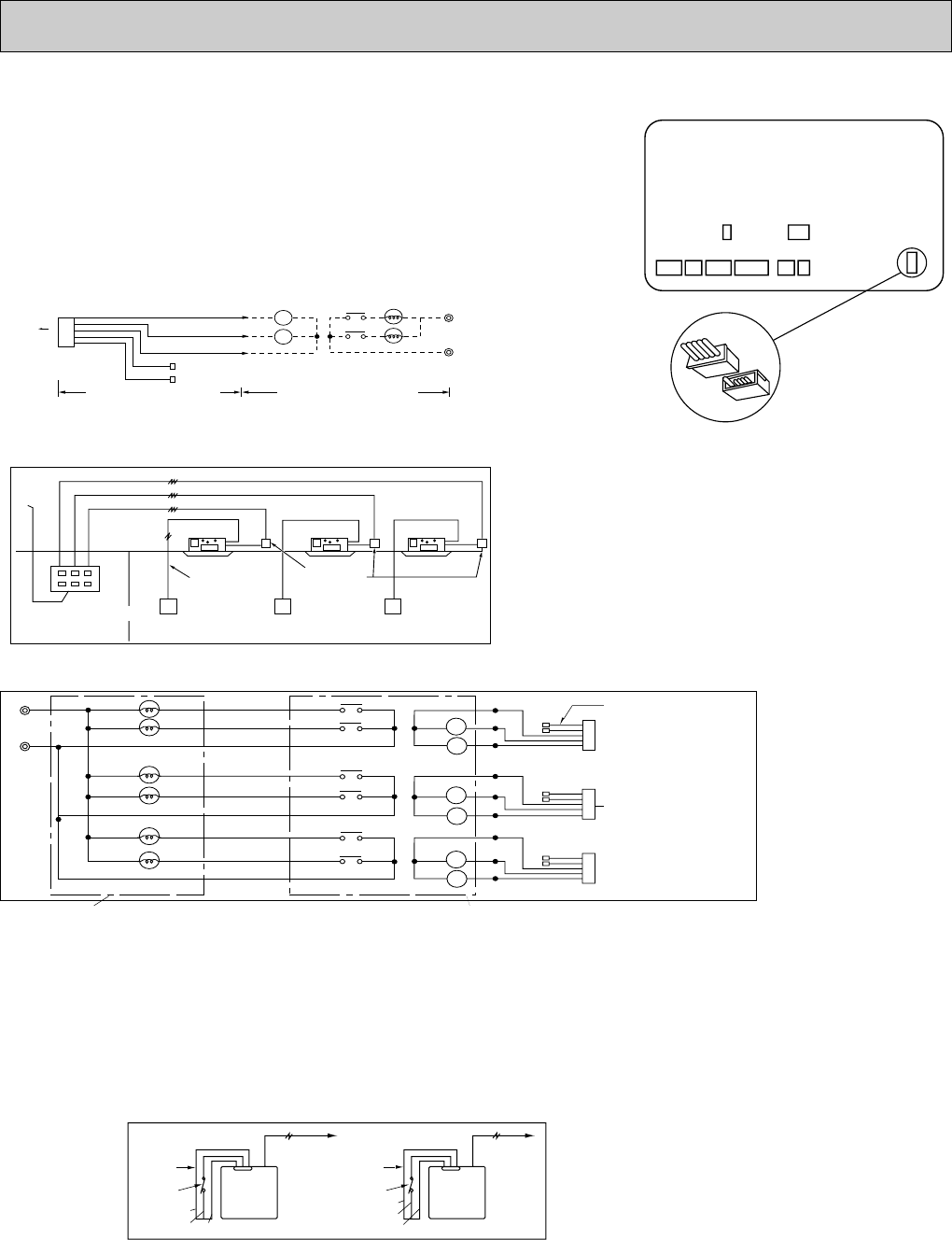
You can control several units with a multiple remote control display, by
wiring an optional multiple display adapter (PAC-SA88HA-E) with relays
and lamps on the market.
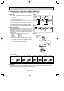
How to wire
(1) Connect the multiple display adapter to the connector CN51 on the
indoor controller board.
(2) Wire three of the five wires from the multiple display adapter as shown
in the figure below.
7. AUTO RESTART FUNCTION
By setting the dip switch SW1-8 to ON, the air conditioner can be started/stopped by power supply ON/OFF.
If the air conditioner is OFF before the power failure, it will not start operation by power restore.
•This function is mainly to emergency performance when the power supply stops temporarily. Therefore, since the protec-
tion function (for example, clank case heater and prevention from restarting in 3 minutes, etc.) of the device is not operat-
ed, this function should not be used mostly.
[Notes on Signs]
X1:Relay (for operation lamp)
X2:Relay (for check lamp)
RL:Operation Lamp
GL:Check Lamp
[Field supplied parts]
Relays:12V DC with rated coil power
consumption below 0.9W.
Lamps:Matching to power supply voltage.
CN51
connector(5P)
GREEN
Power
supply
Electrical insulation is needed.
Wiring at the actual place
Optional multiple display
adapter
The maximum distance between
indoor board and relay is 33ft.
YELLOW
ORANGE
RED
BROWN
5
X2
X2
GL
RL
X1
X1
1
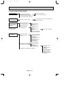
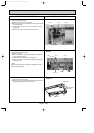
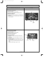
<Wiring >
CN51
Indoor controller board
CN51
Power
supply
Remote
controller
cable
Relay box
(Field supply)
Remote
controller
Remote
controller
Remote
controller
3wires
3wires
3wires
2wires
No.1 unit No.2 unit No.3 unit
Multiple remote control
ON-OFF display
(Field supply)
(Operation check)
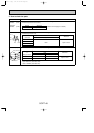
<System>
Power
supply
RL-1
GL-1
Multiple Remote Control Display
Multiple remote
controller adapter
connect to
the connector CN51
Relay box
5
X1-1
X2-1
1
<Wiring diagram>
RL-2
GL-2
RL-3
No.1 unit
GL-3
X1-1
X2-1
X1-2
X1-3
X2-3
X2-2
5
1
No.2 unit
5
1
No.3 unit
X1-2
X2-2
X1-3
X2-3
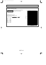
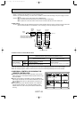
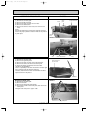
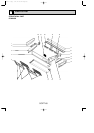
Remote controller
A
B
Brown
Red
Orange
Remote controller
A
B
Brown
Red
Orange
A : an optional timer adapter
B : a single-throw switch
For remote control, connect the optional timer adapter (PAC-SA89TA-E)
<Wiring>
8. TIMER OPERATION OR THE OPERATION BY AN EXTERNAL SIGNAL
OC277--2.qxp 1.12.14 1:42 PM Page 54