


8
7-3. Connecting the Sensors
•
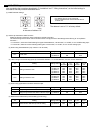
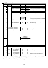
For channel 1, select one of the following four types: Pt100 detection, 4 to 20 mADC, 1 to 5 VDC, or 0 to 10 VDC analog
input.
• For channel 2, select one of the following three types: 4 to 20 mADC, 1 to 5 VDC, or 0 to 10 VDC analog input.
• The wire length depends on the specifications of the sensor. However, since the use of long wires makes the device
susceptible to noise, using wires shorter than 12 m (39.4 ft) is recommended. Use a shielded line for the sensor line
and connect to the FG terminal on this unit or the FG terminal on the control panel.
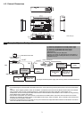
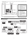
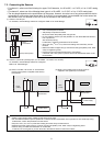
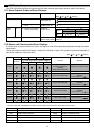
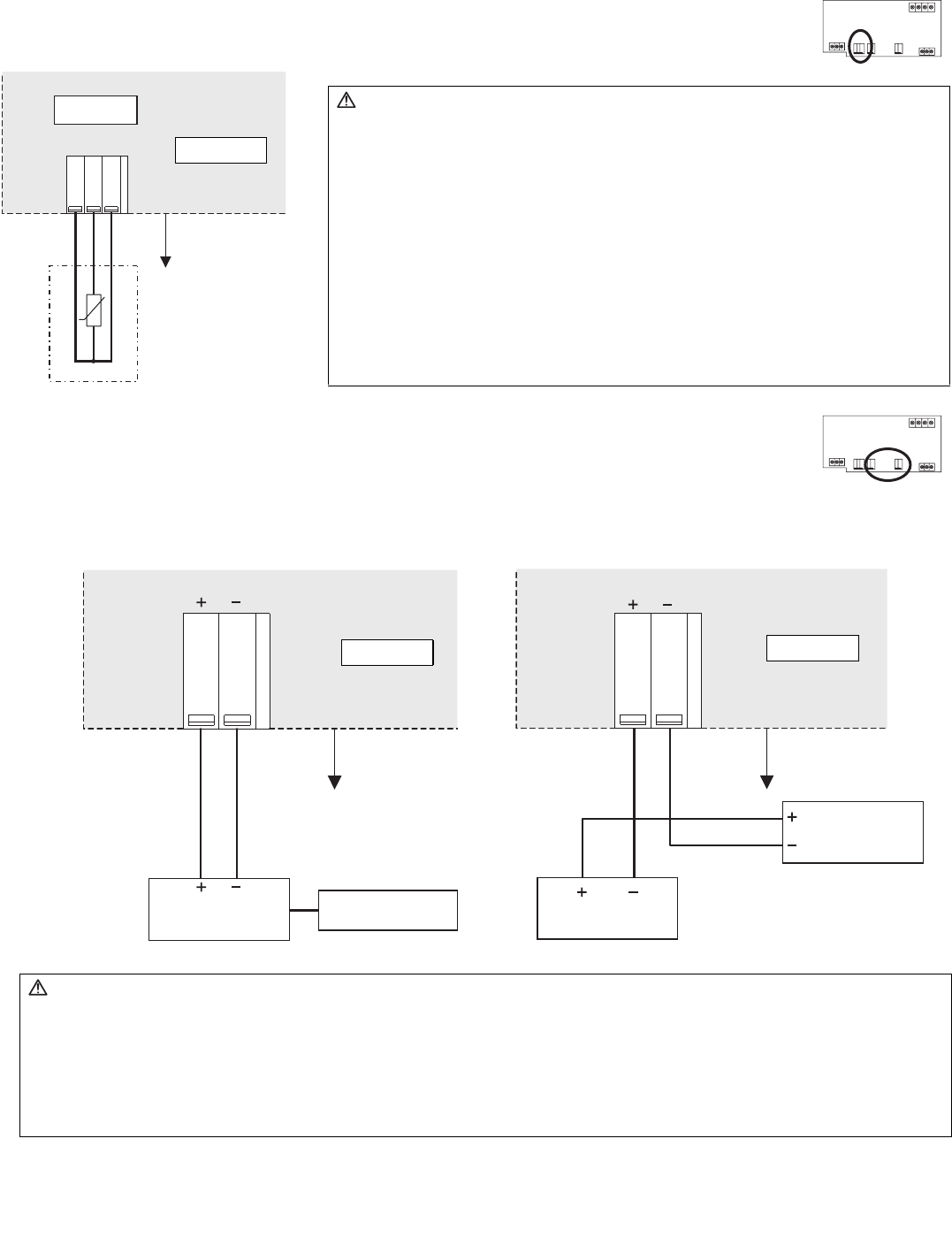
(1) Channel 1 Pt100 Input
To use these, various settings need to be configured. Refer to "8. Initial Settings".
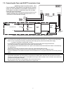
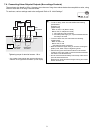
(2) Channel 1 (Channel 2) Analog Input
To use these, various settings need to be configured.
Refer to "8. Initial Settings".
B /
BBA
A / B
CN10
t°
Caution:
• Use a 3-wire system for Pt100.
• A/B polarity is important for Pt100.
Be sure to match the polarity when using Pt100.
• Do not install the sensor input line parallel to or near the M-NET transmission
line or power line.
Also avoid loop wiring.
Furthermore, confirm the precautions for the sensor.
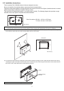
• Strip 12±1 mm (
15
/32 ±
1
/32 in) of the wire coating and insert firmly into the
terminal.
• Make sure that the copper wiring is not short-circuiting the plates (cover, lower
case) or neighboring wires.
• Perform wiring so that the terminal block is not strained.
If strained, use a wire guide or junction terminal to alleviate the stress on the
terminal block.
Pt100 (3-wire system)
Field
Connections
Device side
(4 to 20 mADC, 1 to 5 VDC, 0 to 10 VDC)
CN05
(CN08)
CN05
(CN08)
(a) When 1 to 5 VDC, 0 to 10 VDC, or 4 to 20 mADC
(type for which power is supplied to the sensor)
is connected
Field
Connections
Power supply
Sensor
Sensor
Power supply
(b) When 4 to 20 mADC (type for which power is
supplied to the signal line) is connected
Device side
Field
Connections
Device side
Caution:
• Select a power supply that is suitable for the sensor to be used.
• Do not install the sensor input line parallel to or near the M-NET transmission line or power line. Also avoid loop wiring.
Furthermore, confirm the precautions for the sensor.
• Strip 12±1 mm (
15
/32 ±
1
/32 in) of the wire coating and insert firmly into the terminal.
• Make sure that the copper wiring is not short-circuiting the plates (cover, lower case) or neighboring wires.
• Perform wiring so that the terminal block is not strained.
If strained, use a wire guide or junction terminal to alleviate the stress on the terminal block.