


6
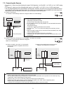
(3) Refer to "7. Wiring Instructions" and connect the wires for the power line, M-NET transmission line, output signal lines, and sensor
input signal lines.
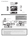
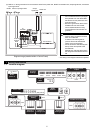
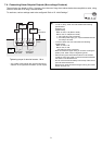
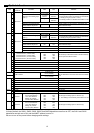
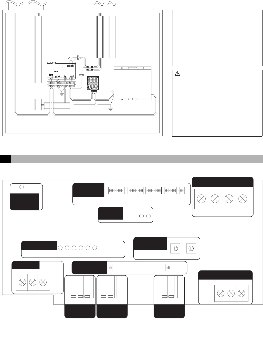
7-1. Terminal Diagram
PAC
-
SC50KUA
M-NET
NFG L-V+V
Diagram Image (Installed within a Control Panel)
* The wiring in the diagram has been simplified.
M-NET Sensor input signal lines
Power line
AI
controller
Note:
• Do not install the sensor input signal
lines parallel to or near the M-NET
transmission line or power line. Also
avoid loop wiring.
• Be sure to ground this device, PAC-
SC50KUA and 24 VDC Power
source. Measurement accuracy
may be affected if devices are not
grounded.
Caution:
• Perform wiring so that the terminal
block is not strained.
If strained, use a wire guide or
junction terminal to alleviate the
stress on the terminal block.
•
Do not connect the wires directly from
the top of the control panel to the
terminal block.
Moisture may enter this device along
the wiring and cause electric shock or
fire.
24 VDC
Power
source
Relay
Junction
terminal
block
Output
signal lines
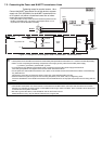
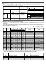
7 Wiring Instructions
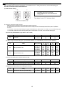
CN01
CN03
CN02
CN10 CN05 CN08
SW11
SW12
SW03
SW01
SW08
SW02
SW09
SW06 SW07
LED03
/
02
A / B / S
V+ / V- / FG
LED17
LED11/ 12/ 13/ 14/ 15/ 16
Function
Settings
M-NET
power on
Output
LEDs
Non-voltage Contact
Output
M-NET
Address
Status LEDs
M-NET
Analog Input
Setting
Channel 1
Pt100 Input
Channel 1
Analog Input
Channel 2
Analog Input
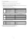
24 VDC Power Supply
10s
1s
(CPU power on)