


10
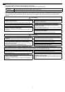
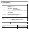
After completing the procedures described in "6. Installation" and "7. Wiring Instructions", set the initial settings in
accordance with the procedure described below.
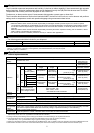
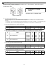
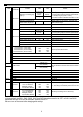
(1) M-NET address settings
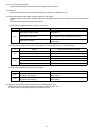
(2) Use the dip switches to select functions.
Select the function required for each input/output channel to be used.
The switch assignment for each channel is shown below. Configure each of the settings while referring to "9. Dip Switch
Functions ".
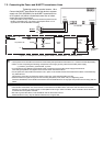
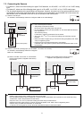
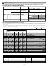
• For channel 1, select one of the following four types: Pt100 detection, 4 to 20 mADC, 1 to 5 VDC, or 0 to 10 VDC analog input.
• For channel 2, select one of the following three types: 4 to 20 mADC, 1 to 5 VDC, or 0 to 10 VDC analog input.
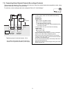
(a) When using Pt100 detection (only channel 1 can be used)
(b) When using one of the analog inputs (4 to 20 mADC detection, 1 to 5 VDC detection, and 0 to 10 VDC detection)
(c) When using upper/lower limit alarm interlock output
(d) Measurement data backup interval setting (for servicing)
8 Initial Settings
Note:
• An address from 01 to 50 can be set.
• Set an address that is not the same as that of
another unit.
The address is set to "01" at factory default.
SW06 SW07
1s
10s
In the case of address "41"
Ch Setting Setting Switch Pt100 To not use
Ch1 Pt100 used
(1) SW01-1
(2) SW01-3
ON
ON
OFF
OFF
Ch Setting Setting Switch
4 to
20 mADC
1 to
5VDC
0 to
10 VDC
To not
use
Ch1 Setting of sensor to use
(1) SW11-1
(2) SW11-2
(3) SW01-1
(4) SW01-2
(5) SW01-3
ON
ON
ON
OFF
OFF
OFF
ON
ON
OFF
OFF
OFF
OFF
ON
ON
OFF
OFF
OFF
OFF
OFF
OFF
Ch2 Setting of sensor to use
(1) SW12-1
(2) SW12-2
(3) SW02-1
(4) SW02-2
ON
ON
ON
OFF
OFF
ON
ON
OFF
OFF
OFF
ON
ON
OFF
OFF
OFF
OFF
Ch Setting Setting Switch To use To not use
Ch1 Usage of upper/lower limit alarm interlock output (1) SW01-5 ON OFF
Ch2 Usage of upper/lower limit alarm interlock output (1) SW02-5 ON OFF
Ch Setting Setting Switch 1 min 2 min 5 min 10 min
Common Measurement data backup interval setting
(1) SW03-1
(2) SW03-2
OFF
OFF
OFF
ON
ON
OFF
ON
ON