


9
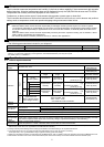
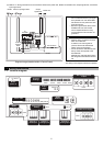
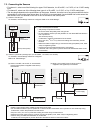
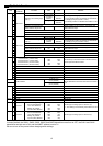
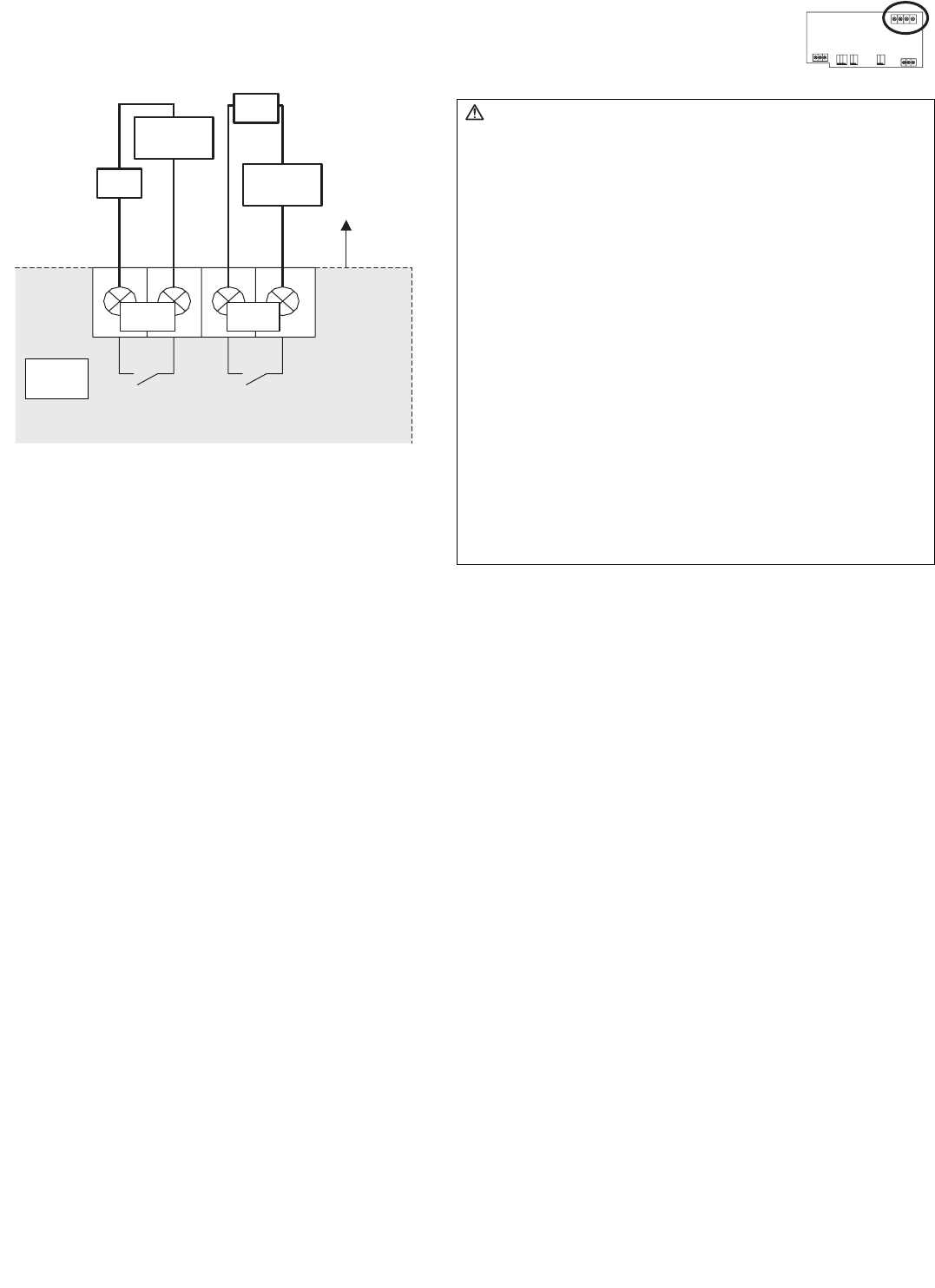
7-4. Connecting Alarm Setpoint Outputs
The maximum wire length is 100 m. However, since the use of long wires makes the device susceptible to noise, using
wires no more than 10 m long is recommended.
To use these, various settings need to be configured. Refer to "8. Initial Settings".
(Non-valtage Contacts)
CN03
Ch1 Ch2
X1
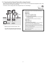
Caution:
• To use X1 relay, obtain one that satisfies the following
specifications.
Operating coil
[Applied load]
MAX: 24 VDC, 5 W (Built-in diode)
MIN: 5 VDC, 2 mW (Built-in diode)
*1 AC loads cannot be connected.
*2 Provide a power supply (V1, V2) that matches the load
and relay to be used.
• To drive a direct load, use ones within the following.
[Applied load]
MAX: 24 VDC, 5 W
MIN: 5 VDC, 2 mW
* AC loads cannot be connected.
• Make sure that the copper wiring is not short-circuiting the
plates (cover, lower case) or neighboring wires.
• Perform wiring so that the terminal block is not strained.
If strained, use a wire guide or junction terminal to alleviate
the stress on the terminal block.
• Do not connect the wires directly from the top of the control
panel to the terminal block.
Moisture may enter this device along the wiring and cause
electric shock or fire.
Tightening torque for terminal screws: 1 N·m.
* The contact of the internal relay is always ON during
detection of an upper/lower limit alarm. (Level output)
Field
Connections
Upper/lower
limit alarm
Upper/lower
limit alarm
Load
Power supply
V1 (DC)
Power supply
V2 (DC)
Device
side