3
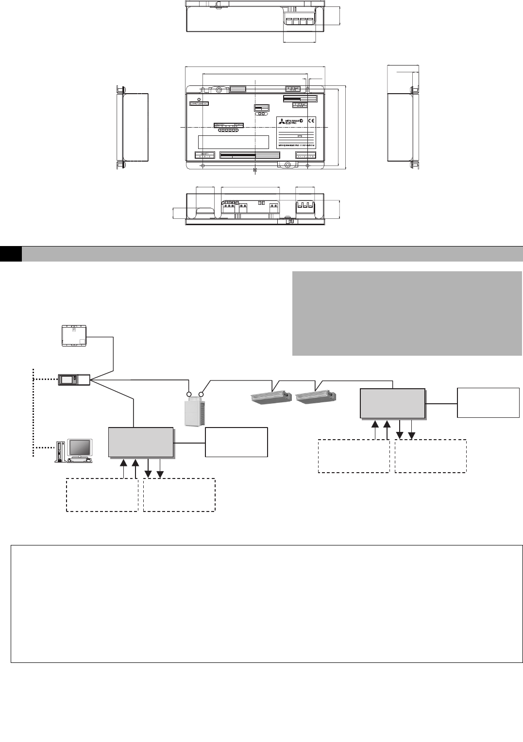
4-2. External Dimensions
[ 24 VDC Power Supply]
N623
Al controller
PAC-YG63MCA
MODEL
SERVICE REF. PAC-
INPUT
WEIGHT
SERIAL No.
MADE IN JAPAN
YG60MCA-J
VOLTAGE
DC24V;0.2A
0.6 kg / 1 /
3
8
lb
Al controller
PAC-YG63MCA
[
Output LEDs
]
Alarm Alarm
Ch2Ch1
[
OUTPUT
]
Non-voltage Contact Output
Alarm Alarm
Ch2Ch1
[ INPUT ]
Pt100 4 to 20 mA / 1 to 5 V / 0 to 10 V 4 to 20 mA / 1 to 5 V / 0 to 10 V
Ch1 Ch2
harmful interference, and (2)this device must accept any interference
received, including interference that may cause undesired operation.
subject to the following two conditions: (1)this device may not cause
This device complies with Part15 of the FCC Rules.Operation is
200
(
7
7
/
8
)
46
(
1
13
/
16
)
26
(
1
1
/
32
)
45
(
1
25
/
32
)
9
(
3
/
8
)
15
(
19
/
32
)
110
(
4
11
/
32
)
26
(
1
1
/
32
)
120
(
4
3
/
4
)
150
(
5
29
/
32
)
26
(
1
1
/
32
)
83.5
(
3
5
/
16
)
27
(
1
3
/
32
)
4.5
(
3
/
16
)
Unit: mm (in)
5 Example of System Configuration
M-NET
TB7
TB3
M-NET
LAN
(2)
(3) (4)
(1)
(2)
(3) (4)
(1)
Centralized control line
Indoor control line
AI controller
G-50A or GB-50A
Power supply unit
PAC-SC50KUA
G(B)-50A Web or TG-2000A
CITY MULTI
(1) Channel 1 temperature or humidity sensor input
(2) Channel 2 temperature or humidity sensor input
(3) Channel 1 upper/lower limit alarm output
(4) Channel 2 upper/lower limit alarm output
<Restrictions>
Maximum of 50 units per G(B)-50A
However, the number of units that can be connected to a
G
(B)-50A is up to 50 including this device, an indoor unit,
LOSSNAY unit, etc.
Temperature sensor,
humidity sensor,
etc.
AI controller
24 VDC Power
Supply
24 VDC Power
Supply
Upper/lower limit
alarm interlock
devices, etc.
Temperature sensor,
humidity sensor,
etc.
Upper/lower limit
alarm interlock
devices, etc.
* This figure omits the power supply line and only shows the transmission line.
Note:
• For the shield ground of the M-NET centralized control line, use single-point grounding at the power unit for the transmission
line.
However, when supplying electric power to the M-NET centralized control line from the R410A series outdoor unit without
using a power supply unit for the transmission line, use single-point grounding at the TB7 of that outdoor unit.
Furthermore, when connecting the M-NET transmission line of this device to the M-NET indoor control line, use grounding
at the TB3 for each outdoor unit system.
• If the M-NET transmission line of this device is connected to an M-NET indoor control line and the outdoor unit is down
because, for example, the power supply is interrupted for servicing or there is a failure, the AI controller cannot be set and
monitored from the system controller.
• The sensor connected to the AI controller can only be monitored from G(B)-50A Web browser and TG-2000A. The sensor
cannot be monitored from the G-50A LCD.


