


2
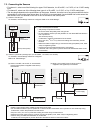
The AI controller measures temperature and humidity; it also has an alarm capability if the measurement data exceeds
defined setpoints. Historical measurement data can be displayed via only the G(B)-50A Web browser and TG-2000A.
Temperature and humidity cannot be displayed on the G-50A LCD.
Furthermore, an alarm can be output if measurement data exceeds a preset upper or lower limit.
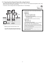
The AI controller also features a function that interlocks M-NET devices for indoor units, etc. set in advance and performs
settings such as temperature control and operation/stoppage using measurement data values.
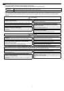
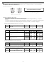
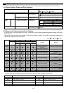
• The following parts should be included in your shipment:
* In addition to the parts listed above, see your local Mitsubishi Electric dealer to purchase the other parts necessary to operate this device (Refer to
section 6-1). Furthermore, depending on the application, other Mitsubishi Electric parts may be required.
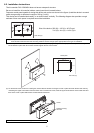
For details, refer to "6. Installation".
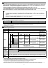
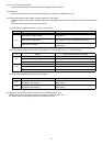
4-1. Device Specifications
*1: Supply electric power from a power supply unit for the transmission line or an outdoor unit. Furthermore, the power consumption factor of the M-
NET circuitry of this unit is "1/4" (equivalent to one ME Remote Controller).
*2: Configure the dip switch settings for the analog input method to use while referring to "9. Dip Switch Functions".
*3: The measurement error for the system includes the measurement error for this unit, sensor, and wiring.
a%FS (full scale) = a% × ([measurement range's upper limit value] - [lower limit value])
*4: Settings for the interlock function are performed from the Maintenance Tool. For details, refer to the operation manual for the Maintenance Tool.
*5: M3 and M3.5 are sizes of the screw on the terminal block (ISO metric screw thread). The number indicates the screw diameter (mm).
2 Usage
Caution: Usage Restrictions
• Mitsubishi Electric does not take financial responsibility for damages caused by issues beyond our control or special
circumstances (predicable or unpredictable); and secondary or accidental damages, and damages to other objects. We also
do not take financial responsibility for opportunities lost as a result of device failure, or electrical power failure at the end-
user site.
Mitsubishi Electric does not take financial responsibility caused by end-users' requests including, but not limited to, device
testing, startup, readjustment and replacement.
• Do not use this device in disaster prevention security or "critical to life" applications.
3 Parts List
Number Part Name Quantity
1 AI controller 1
2 Installation/instruction manual (this document) 1
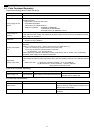
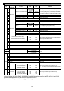
4 Specifications
Item Description
Power
Supply
24 VDC±10%: 5 W
Screw terminal
block (M3) (*5)
Interface
M-NET communication 17 to 30 VDC (*1)
Screw terminal
block (M3) (*5)
Input
Ch Sensor
Measurement
target
Measurement
range
Measurement error
External
connection method
Ch1
Pt100
(3-wire system)
Temperature
-30 to 60°C
[-22 to 140°F]
±0.3%FS ±0.1°C (0.18°F)
(*3)
[at 25°C (77°F)]
Screwless terminal
block (3 poles)
Analog
4 to 20 mADC
Temperature/
humidity
(Set by system
controller)
±0.5%FS ±0.1°C (0.18°F)
(*3)
±0.5%FS ±0.1%RH
[at 25°C (77°F)]
Screwless terminal
block (2 poles)
1 to 5 VDC
0 to 10 VDC
Ch2
Analog
4 to 20 mADC
Temperature/
humidity
(Set by system
controller)
±0.5%FS ±0.1°C (0.18°F)
(*3)
±0.5%FS ±0.1%RH
[at 25°C (77°F)]
Screwless terminal
block (2 poles)
1 to 5 VDC
(*2) 0 to 10 VDC
Output
Upper/lower limit
alarm interlock output
(non-voltage contact)
Applied load
MAX: 24 VDC, 5 W
MIN: 5 VDC, 2 mW
* AC loads cannot be connected.
Screw terminal
block (M3.5) (*5)
Interlock
Function
Interlock M-NET devices according to measurement data values. (*4)
Environment
Conditions
Temperature
Operating temperature range 0 to 40°C [32°F to 104°F]
Storage temperature range -20 to 60°C [-4°F to 140°F]
Humidity 30 to 90%RH (no condensation)
Dimensions 200 (W) × 120 (H) × 45 (D) mm / 7
7
/8 (W) × 4
3
/4 (H) × 1
25
/32 (D) in
Weight 0.6 kg / 1
3
/8 lb
Time Backup
During Power
Failure
In the event of power failure or shut-off, the internal capacitor will continue to track time for approximately one week.
(The internal capacitor takes about 24 hours to fully charge; a replacement battery is not necessary.)
Installation
Environment
Inside a control panel (indoors)
* Use this product in a hotel, a business office environment or similar environment.