882108-YIM-B-1012
14 Johnson Controls Unitary Products
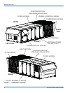
SERVICE ACCESS
Access to all serviceable components is provided by the fol-
lowing hinged doors:
• Furnace compartment
• Supply Air Fan compartment Evaporator Coil compart-
ment (three doors)
• Filter compartment economizer compartment (two doors)
• Power Exhaust compartment (two doors)
• Main control panels (one door)
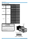
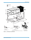
Refer to Figure 1 for location of these access panels.
COMPRESSORS
Units are shipped with compressor mountings factory-
adjusted and ready for operation.
FILTERS
Throwaway or rigid filters are supplied with each unit. Filters
must always be installed ahead of evaporator coil and must
be kept clean or replaced with same size and type. Dirty fil-
ters will reduce the capacity of the unit and will result in
frosted coils or safety shutdown. Required filter sizes are
shown in Table 15. The unit should not be operated without
filters properly installed.
THERMOSTAT (CONSTANT VOLUME UNITS)
The thermostat, if used, should be located on an inside wall
approximately 56 inches above the floor where it will not be
subject to drafts, sun exposure or heat from electrical fixtures
or appliances. Follow manufacturer's instructions enclosed
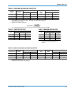
with sensor for general installation procedure (See Figure 5).
Refer to Table 13 for control wire sizing and maximum length.
SPACE SENSOR (VARIABLE AIR VOLUME UNITS)
The space sensor, if used, should be located on an inside
wall approximately 56 inch above the floor where it will not be
subject to drafts, sun exposure or heat from electrical fixtures
or appliances. Follow manufacturer's instructions enclosed
with sensor for general installation procedure.
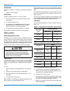
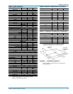
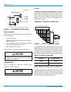
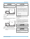
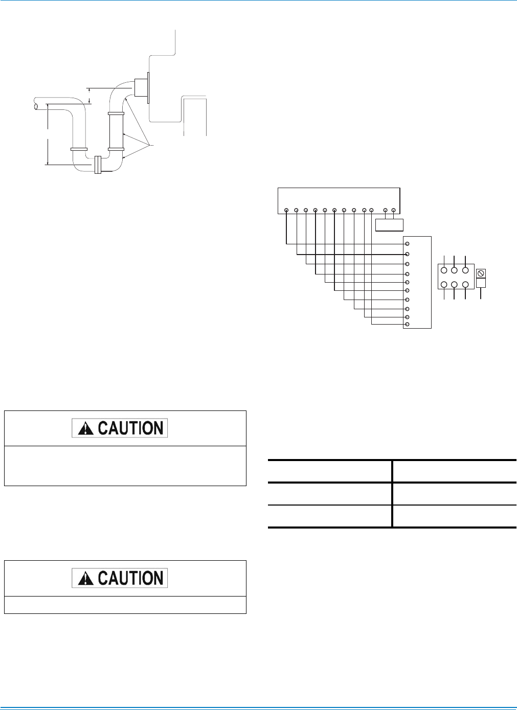
FIGURE 4 - RECOMMENDED DRAIN PIPING
Make sure that all screws and panel latches are
replaced and properly positioned on the unit to
maintain an air-tight seal.
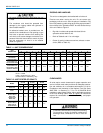
DO NOT loosen compressor mounting bolts.
H - 1 / 2 " P L U S T O T A L S T A T I C P R E S S U R E - M I N I M U M
Y - M I N I M U M 2 "
Y
F IE L D S U P P L I E D
D R A I N C O N N E C T I O N
F A C T O R Y I N S T A L L E D
U N I T B A S E
H
R O O F
C U R B
O R
P E R IM E T E R
S U P P O R T
S T R U C T U R E
FIGURE 5 - TYPICAL THERMOSTAT WIRING
TABLE 13: CONTROL WIRE SIZES
WIRE SIZE MAXIMUM LENGTH
20 AWG 100 Feet
18 AWG 150 Feet
R C G Y 1 Y 2 Y 3 Y 4 W 1 W 2 A 1 C T T
R
G
Y 1
Y 2
Y 3
Y 4
W 1
W 2
A 1
C
R E M O T E
S E N S O R
2 T H O 4 7 0 2 2 2 4
T 7 3 0 0 T H E R M O S T A T S U B B A S E
L 1
L 2 L 3
A
B
C
T B 1
E Q U IP . G N D .
P O W E R S U P P L Y
P O W E R W IR IN G


