


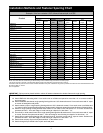

Installation Methods and Fastener Spacing Chart
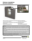
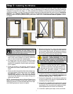
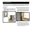
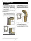
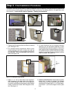
Step 4: Installing the Window
8
IMPORTANT: Follow ALL fastener methods in the corresponding box.
Example: If the box contains A,B,E; follow all instructions for A,B,E.
Product
Installation Method
Wood BMC/Flat Casing Masonry Clips Screws
StormPlus
Impact
Zones
Fastener
Method
StormPlus
Impact
Zones
Fastener
Method
StormPlus
Impact
Zones
Fastener
Method
Jamb
Fastener
Length
Sill Fastener
Length
CCM Awning 2, 3 C, E 2, 3 D, E 3″ 2″
CCM Operator 2, 3 C, E 2, 3 D, E 3″ 2″
CCM Round Top Operator 3 C, E 3 D, E 3″ 2″
CCM Picture 1″ 2, 3 C, E 2, 3 D, E 3″ 2″
CCM Picture Round Top 1″ 3 C, E 3 D, E 3″ 2″
CCM Stationary 3/4″ 2, 3 C, E 2, 3 D, E 3″ 2″
CCM Round Top Stationary 3/4″ 3 C, E 3 D, E 3″ 2″
CDG Polygon 2, 3 C, F 2, 3 D, E* 3″ 3″
CDG Round Top 2, 3 C, F 2, 3 D, E* 3″ 3″
CUDH 2, 3** C 2, 3 D 21/2″ N/A
CUDH Picture 2″ 2, 3** C 2, 3 D, G 21/2″ N/A
CUDH Transom 1 5/8″ 2, 3** C 2, 3 D, G 21/2″ N/A
CUDH RT/Polygon 3** C 3 D 21/2″ N/A
CUDH Magnum N/A C N/A H Supplied N/A
CUDH Magnum Picture/Transom N/A C N/A H Supplied N/A
WCM Awning 2, 3 A, B, E 2, 3 C, E 2, 3 D, E 3″ 31/2″
WCM Operator 2, 3 A, B, E 2, 3 C, E 2, 3 D, E 3″ 31/2″
WCM Round Top Operator 3 A, B, E 3 C, E 2, 3 D, E 3″ 31/2″
WCM Picture 1″ 2, 3 A, B, E 2, 3 C, E 2, 3 D, E 3″ 31/2″
WCM Stationary 3/4″ 2, 3 A, B, E 2, 3 C, E 2, 3 D, E 3″ 31/2″
WCM Round Top Stationary 1″ 3 A, B, E 3 C, E 2, 3 D, E 3″ 31/2″
WDG Polygon/Round Top A, B, F A, B, E 2, 3 C, F 2, 3 D, E* 3″ 31/2″
WUDH A, B A, B, E 2, 3 C 2, 3 D 21/2″
WUDH Picture/Transom A, B A, B, E 2, 3 C 2, 3 D, G 21/2″
WUDH Picture/Transom RT/Polygon 2, 3 C 2, 3 D, G 21/2″
WUDH Magnum N/A C N/A H Supplied N/A
WUDH Magnum Picture N/A C N/A H Supplied N/A
NOTE: Units with clad brick mould casing or clad flat casing must be installed using wood screws or masonry clips.
* Sill screws required on all sizes. Use appropriate fastener length from table above and requirements in detail “F”.
**StormPlus UDH IZ3 products have two storm brackets attached to each jamb. Installations using masonry brackets must have the storm brackets fastened to the
RO with two #8x2 1/2″ screws.
N/A: Not applicable.
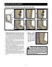
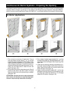
A. Attach BMC with 16d casing nails 2″ from each corner on all sides and spaced no more than 10″ on center around the
entire perimeter.
B. Attach installation brackets to rough opening framing with one 1 5/8″ sheetrock screw 6″ from each corner and 12″ apart
on center at head jambs and jambs.
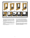
C. Attach masonry clips to rough opening framing with two 1 5/8″ sheetrock screws 5″ from each corner on all sides and
12″ apart on center around the entire perimeter. Angle screws 15 degrees toward the center thickness of the wood buck.
D. Attach to rough opening framing with #8 wood screws 6″ from each corner and spaced 12″ on center. Screws must
penetrate at least 1″ from each edge of wood framing at a depth of no less than 1 1/4″.
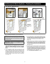
E. On units 28″ or wider, attach frame sill to rough openingframing with a #8 wood screw 5″ from each corner and 15″ apart
on center. Screws must penetrate at least 1″ from each edge of wood framing at a depth of no less than 1 1/4″
F. Attach sills to rough opening framing with a #8 wood screw 6″ from each corner and 12″ apart on center. Screws must
penetrate at least 1″ from each edge of wood framing at a depth of no less than 1 1/4″.
G. Attach three masonry clips on both jambs within 6″ of the bottom corner.
H. Attach through all pre--drilled holes in jamb and head jamb.
Fastener Methods
IMPORTANT: Shims must be placed behind or above all fasteners between the window frame and rough opening.