


3
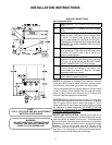
SERVICE CONNECTIONS:
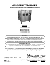
Gas Operated Boilers
G GasConnection - 3/4” (19mm) IPS (100 & 200K
BTU)
G1 Gas Connection - 1” (25mm) IPS (275 & 300K
BTU)
CW1 Cold Water - 3/8” (10mm) O.D. tubing for cold
water to boiler. Cold water lines will have a max
of 50PSI (3.5 kg/cm
2
) and a min of 25PSI (1.8
kgcm
2
) water pressure. CAUTION: FILTER SYS-
TEM INSTALLATION INSTRUCTIONS MUST BE
ADHERED TO WHEN CONNECTING A FILTER
TO THIS LINE.
CW2 Cold Water - 3/8” (10mm) O.D. tubing for cold wa-
ter to condenser. Cold water lines will have a max
of 50PSI (3.5 kg/cm
2
) and a min of 25PSI (1.8
kg/cm2) water pressure.
D Drain - Pipe full 2” (51mm) IPS to ush oor drain
capable of receiving water owing at a max rate
of 5 gal. (19 liters) per minute. DO NOT MAKE
SOLID CONNECTION TO FLOOR DRAIN.
EC Electrical Connection - 120 volt A.C. 60Hz, 1/2”
(13mm) conduit connection or equivalent. Use
wire suitable for a least 90
o
C. Amp for 115 steam
generator controls is 2 amps.
ST Steam Take-off - Connection for operation of ad-
jacent steam powered equipment.
NOTES: If equipment is installed where elevation exceeds
2,000 feet (609.6 meters) above sea level, specify installa-
tion altitude so that proper gas orices can be provided.
The only available space to supply utilities to the gas boiler
is the 6” (152mm) space between the oor and the cabinet.
Allow 3” (76mm) space from side wall and 6” (152mm) from
real wall if adjoining walls are combustible.
CAUTION: Before connecting water to this unit, water sup-
ply should be analyzed to make sure hardness is no greater
than 2.0 grains and pH level is within the range of 7.0-8.5.
Water which fails to meet these standards should be treated
by installation of water conditioner. EQUIPMENT FAILURE
CAUSED BY INADEQUATE WATER QUALITY IS NOT
COVERED UNDER WARRANTY.
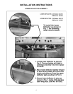
WASTE LINE INSTALLATION: The drain port of the unit is
marked with a colored tag and is located at the lower rear left
side of the boiler as viewed from the front. This exhaust line
may be left open if the boiler has to be situated in a tiled oor
depression or a tiled curb section that is equipped with drain
facilities. If this is not the case, then a 2” (51mm) NPT.
drain line must be connected to divert the exhaust to the
oor drain. If it is necessary to use more than three elbows,
increase the size of the waste line accordingly.
INSTALLATION INSTRUCTIONS
NOTE:
PVC & CPVC PIPE ARE NOT ACCEPTABLE
MATERIALS FOR DRAINS.
WARNING:
DO NOT UNDER ANY CIRCUMSTANCE
CONNECT THE EXHAUST DRAIN LINE
DIRECTLY TO A SEWER LINE.