


10
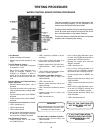
TESTING PROCEDURE
WATER CONTROL BOARD TESTING PROCEDURE
This test procedure is to be used to determine if the
control is working properly. It is not intended to de-
termine why the control may have failed.
If testing shows that the control is operating properly,
check all probe and solenoid wiring and the condi-
tion of the electrodes in the steam chamber.
Contact the factory if the boiler still does not operate
properly after completing the testing.
Tools Needed:
Digital or Analog V-O-M meter.
Alligator clip type test jumpers (2 sets
min.).
Turn Off Power to Control:
Use V-O-M to verify there is no power
at terminals L 1 & L2.
Use V-O-M to verify that there is no
power at terminals ‘FW(NO)’, ‘LO
LlTE(NC)’ & ‘HTR(NO)’. If there is
power at any of these terminals, you
will need to nd the source and turn
it off.
Remove Wires from Probe and Relay
Switch Terminals:
DO NOT remove wires from L 1 & L2
terminals.
Tag wires and remove from probe and
relay contact terminals including ‘GND’
terminal.
Tag and remove wires from ‘RESET’
terminals.
Connect jumper wire to both ’RESET’
terminals.
Turn Power On to Terminals L 1 & L2:
‘LED l’ should turn on.
‘LED 2’ should be off.
‘LED 3’ should be off.
Use V-O-M to verify that there is power
at ‘FW(NO)’ & ‘LO LlTE(NC)’ terminals
and no power ‘HTR(NO)’ terminals
Test Feedwater Function:
Connect jumper wire to ‘FW HIGH’
and ‘GND’ terminals.
»
»
»
»
»
»
»
»
»
»
»
»
»
‘LED l’ should turn off after a 10 sec-
ond delay.
Use V-O-M to verify that there is no
power at the ‘FW (NO)’ terminal.
Remove jumper from ‘FW HIGH’ and
‘GND’ terminals. . ‘LED l’ should turn
on.
Use V-O-M to verify that there is pow-
er at the ‘FW(NO)’ terminal.
Test Primary Low Water Function:
Connect jumper wire to ‘LW(1) and
‘GND’ terminals.
‘LED 3’ should turn on.
Remove jumper wire from ‘LW(1)’ and
‘GND’ terminals.
‘LED 3’ should turn off after a 3 second
delay.
Connect jumper wire to ‘LW(1)’ and
‘GND’ terminals.
‘LED 3’ should turn on.
IMPORTANT:
Jumper wire between ‘LW(1) and ‘GND’
terminals must remain in place to test
secondary low water function.
Test Secondary Low Water Function:
Connect jumper wire to ‘LW(2)’ and
‘GND’ terminals.
‘LED 2’ should remain off.
»
»
»
»
»
»
»
»
»
»
»
»
»
Use V-O-M to verify that there is pow-
er at the ‘LO LlTE(NC)’terminal and no
power at the ‘HTR(NO)’ terminal.
Remove the jumper wires from the
‘RESET’ terminals.
‘LED 2’ should turn on.
Use V-O-M to verify that there is no
power at the ‘LO LlTE(NC)’ terminal
and power at the ‘HTR(NO)’ terminal.
Connect jumper wire to ‘RESET’ ter-
minals.
Remove jumper wire from ‘LW(2)’ and
‘GND’ terminals.
‘LED 2’ should turn off after a 3 second
delay.
USE V-O-M to verify that there is pow-
er at the ‘LO LlTE(NC)’ terminal and
no power at the ‘HTR(NO)’ terminal.
Connect jumper wire from ‘LW(2)’ and
‘GND’ terminals.
‘LED 2’ should remain off.
IF ANY OF THE FUNCTIONS DO
NOT WORK, REPLACE THE
BOARD!
IF ALL FUNCTIONS WORK,
TROUBLE-SHOOTING OTHER
COMPONENTS WILL BE
REQUIRED!
»
»
»
»
»
»
»
»
»
»