


9
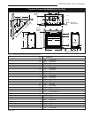
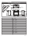
DVB4136 Direct Vent Gas Fireplace
20012322
Always check for gas leaks with a mild
soap and water solution applied with a
brush no larger than 1” (25 mm). Never
apply soap and water solution with a spray
bottle. Do not use an open flame for leak
testing.
The fireplace valve must not be subjected
to any test pressures exceeding 1/2 psi.
Isolate or disconnect this or any other gas
appliance control from the gas line when
pressure testing.
The gas control is equipped with a captured screw type
pressure test point, therefore it is not necessary to pro-
vide a 1/8” test point up stream of the control.
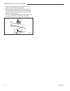
When using copper or flex connector use only approved
fittings. Always provide a union when using black iron
pipe so that the gas line can be easily disconnected for
burner or fan servicing. (Fig. 6) See the gas specifica-
tions for pressure details and ratings.
Remote ON/OFF Switch Installation
Do not wire the remote ON/OFF wall switch for this gas
appliance into a 120v power supply.
1. Thread wire through the electrical knockout located
on either side of the unit. Take care not to cut the
wire or insulation on metal edges. Ensure the wire is
secured and protected from possible damage. Run
one end of the gas control valve and the other end to
the conveniently located wall switch.
2. Attach the wire to the ON/OFF switch and install
switch into receptacle box. Attach cover plate to
switch.
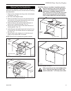
3. Connect wiring to gas valve. (Fig. 7)
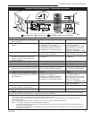
FP297A
INSTA VENT FREE
UVHB26 GAS SUPPLY
7/1/98
1/2” Gas Supply
1/2” NPT x 3/8” Flare Shut-
off Valve
3/8” Flex Line
(from valve)
FP297a
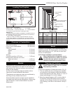
Fig. 6 Typical gas supply installation.
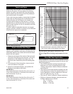
TPTH
TH
TP
FP1218
Remote switch
wiring
8/02
Remote ON/OFF
Switch
FP1218
Fig. 7 Remote switch wiring diagram for R models.
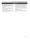
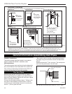
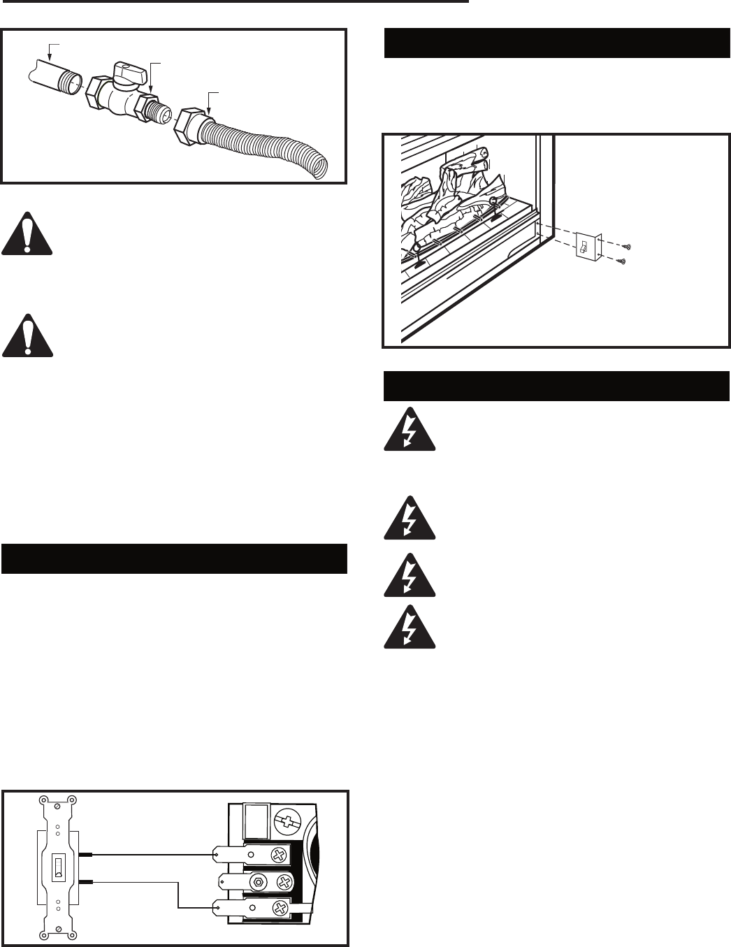
Alternate Switch Location
The remote switch can be installed on either side of
the access door. Mount the switch to the switch bracket
provided. Screw the bracket on either side of the frame,
line up the screws with the prepunched holes. (Fig. 8)
FP1024
alternate
remote switch
location
1/27/00 djt
FP1024
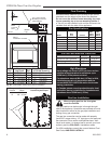
Fig. 8 Alternate switch location.
EB-1 Electrical Box
The fireplace, when installed, must be
electrically connected and grounded in
accordance with local codes or, in the ab-
sence of local codes, with the current CSA
C22.1 Canadian Electrical Code.
For USA installations, follow the local
codes and the national Electrical Code
ANSI/NFPA No. 70.
It is strongly suggested that the wiring of
the EB-1 Electrical Junction Box be carried
out by a licensed electrician.
Ensure that the power to the supply line
has been disconnected before commenc-
ing this procedure.
The EB-1 electrical junction box has been
supplied standard on the DV360/580 models to allow
for the easy installation of an optional fan kit.
To connect the EB-1 box to the house electrical supply,
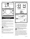
follow the steps below.
1. Unscrew the retaining screw from the EB-1 base
plate (Fig. 9) and remove the EB-1 assembly from
the fireplace.
2. Remove the front cover of the EB-1 box.
3. Remove the plug socket assembly from the EB-1
box.
4. Feed the supply line in from the outside through the
cable clamp. (Fig. 9)
5. Connect black wire of the power supply line to the
brass screw (polarized) of the socket assembly.
6. Connect the white wire of the power line to the
chrome screw of the socket assembly.