


41
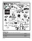
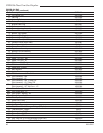
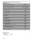
DVB4136 Direct Vent Gas Fireplace
20012322
Conversions must be completed by qualified personnel
Fuel Conversion Instructions
To convert the DVB4136 units for use with a different
gas follow these instructions. Before proceeding, turn
control knob on valve to “OFF” and turn gas supply
OFF. Turn OFF any electricity that may be going to the
appliance.
CAUTION: Logs may be HOT! Allow to cool before
proceeding.
1. Open louvre assembly bottom to gain access to
valve. Remove window frame assembly. (See “Win-
dow Frame Assembly Removal”, Page 24, Fig. 46)
2. Remove logs if previously installed.
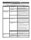
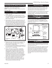
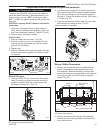
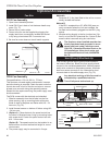
SkyTech Valve
1. Remove rubber cap from valve. (Fig. 65)
2. Push pin in and turn so line on the end of the pin
lines up with the appropriate gas. NAT for natural
gas and LP for propane.
3. Replace cap.
4. Remove minimum rate screw and replace with new
minimum rate screw supplied in kit. Refer to Table 1
on Page 42.
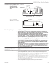
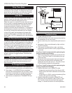
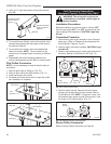
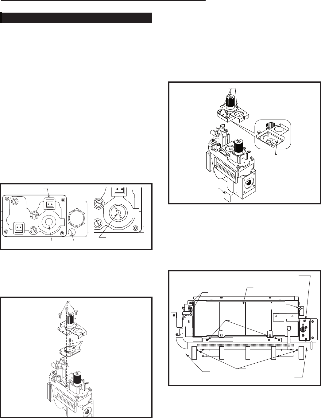
NOVA SIT820 Valve
1. Using the TORX T20 bit, remove and discard the
three (3) pressure regulator mounting screws (A),
pressure regulator tower (B) and the spring and
diaphragm assembly (C). (Fig. 66)
FC107
SIT820
valve conversion
10/03
A
B
C
O
F
F
P
I
L
O
T
O
N
FC107
Fig. 66 Remove mounting screws, pressure regulator tower
and spring and diaphragm assembly.
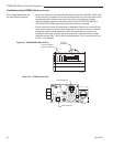
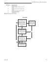
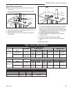
2. Insure the rubber gasket (D) is properly positioned
and install the new HI/LO pressure regulator assem-
bly to the valve using the new screws (E) supplied
with the kit. Tighten the screws securely. (Ref. torque
= 25 in/lb) (Fig. 67)
3. Install the enclosed conversion label (F) to the valve
body where it can easily be seen. (Fig. 67)
Valve conversion is complete.
D
E
F
FC108
SIT
regulator
conversion
10/03
O
F
F
P
I
L
O
T
O
N
FC108
Fig. 67 Replace regulator.
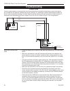
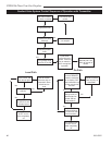
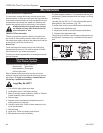
Burner Orifice Conversion
1. Remove the screws that secure the fettle and the
burner tube assembly, located behind the burner
tube assembly. Remove the three (3) screws that
secure the burner housing assembly to the base pan
at the right and left end of the burner housing as-
sembly. (Fig. 68)
2. Remove the fettle and the burner tube assembly.
Slide the burner housing assembly to the right and
up to free the orifice.
Fig. 68 Remove screws holding burner housing assembly
and burner tube assembly.
Burner Housing
Assembly
Pilot Location
Remove
Screws
Burner Tube Assembly
Remove Screws
Remove Screws
Fettle
FP1817
Inlet
PILOT
Pilot Adj.
Outlet
MAIN
FP1769
AF4000 valve face
2/07
Main Connection
Rubber Cap
Gas Type
Marker
FP1769a CO137
Minimum
Rate Screw
Fig. 65 Remove rubber cap and adjust gas type marker.