


7
DVB4136 Direct Vent Gas Fireplace
20012322
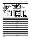
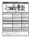
Clearance to Combustibles
Top of unit to ceiling ................................. 36” (914 mm)
Front of unit to combustibles ................... 36” (914 mm)
Appliance
Top of standoff ....................................... 0” (0 mm)
Bottom ..................................................... 0” (0 mm)
Side ......................................................... 0” (0 mm)
Back ........................................................ 0” (0 mm)
Venting
Concentric sections of DV Vent ................... 1” (25 mm)
Nonconcentric sections of DV Vent
Sides and bottom .................................. 1” (25 mm)
Top ........................................................ 2” (51 mm)
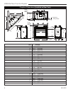
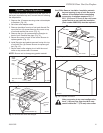
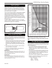
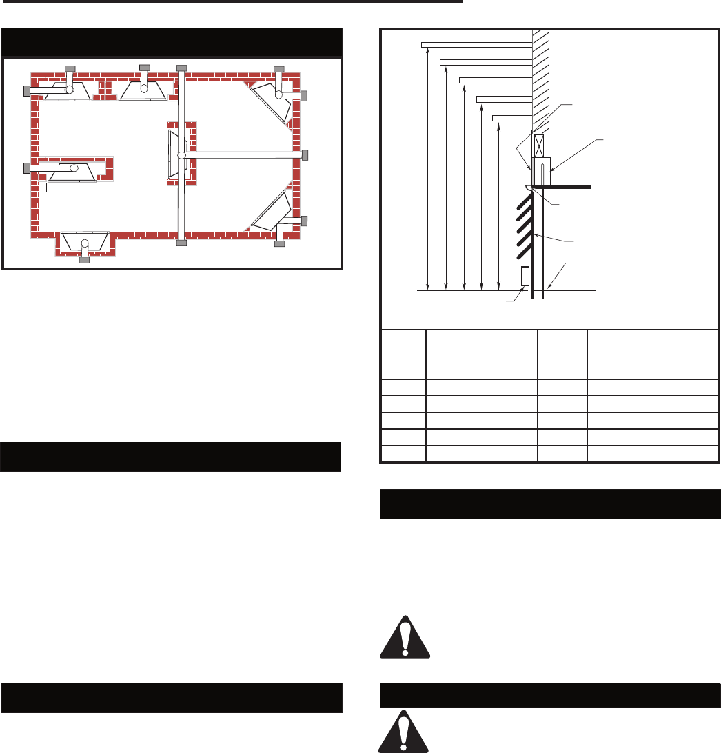
Mantels
The height that a combustible mantel is fitted above the
fireplace is dependent on the depth of the mantel. This
also applies to the distance between the mantel leg (if
fitted) and the fireplace.
For the correct mounting height and widths, refer to
Figures 4a, 4b and the Mantel Chart below.
The distances and reference points are not affected by
the fitting of a bay window front trim kit.
Noncombustible mantels and legs may be installed at
any height and width around the appliance. When using
paint or lacquer, it must be heat resistant to prevent
discoloration.
CFM146
Bottom of Door Trim
Mantel Chart
Mantel Shelf Mantel from Top
Ref. or Breast Plate Ref. of Comb. Chamber
Depth
V 10” (254 mm) A 19” (483 mm)
W 8” (203 mm) B 17” (432 mm)
X 6” (152 mm) C 15” (381 mm)
Y 4” (101 mm) D 13” (330 mm)
Z 2” (51 mm) E 11” (279 mm)
Fig. 4a Combustible mantel minimum installation.
Hearth
A hearth is not mandatory, but is recommended for
aesthetic purposes. We recommend a noncombustible
hearth which projects out 12” (305 mm) or more from
the front of the fireplace.
Cold climate installation recommendation:
When installing this unit against a non-in-
sulated exterior wall or chase, it is manda-
tory that the outer walls be insulated to
conform to applicable insulation codes.
Y
E
A
B
C
D
F
Y
B
X
LU584-1
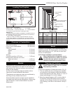
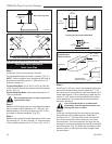
Locating unit
2/4/99 djt
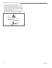
Locating Your Fireplace
LU584-1
A) Flat on wall B) Cross corner C) **Island
D) *Room divider E) *Flat on wall corner F) Chase installation
Y) 0” minimum (Check minimum if mantel leg is used)
NOTE (Fig. 3):
** Island (C) and Room Divider (D) installation is possible as long as
the horizontal portion of the vent system (X) does not exceed 20’ (6
m). See details in Venting Section.
* When you install your fireplace in(D) Room divider or (E) Flat
on wall corner positions (Y), a minimum of 6“ (152 mm) clearance
must be maintained from the perpendicular wall and the front of the
fireplace.
Fig. 3 Locating gas fireplace.
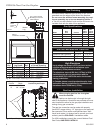
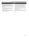
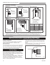
Framing and Finishing
Check fireplace to make sure it is levelled
and properly positioned.
To mount the appliance: Choose the location. (Fig. 5)
1. This unit comes with four (4) flanges pre-mounted
on both sides of the fireplace to allow two different
drywall thicknesses to be used. Flange “A” is for 1/2”
drywall while flange “B“ is for 5/8” drywall.
2. Bend the desired flanges out 90° on both sides of
the fireplace. Slide the fireplace into the framed
opening until the flanges contact the front surfaces
of the framing. Level the unit and secure it firmly in
place.
A B C
D
E
V
W
X
Y
Z
Fireplace
CFM146
DV Mantel Chart
7/5/01 sta
Louvre Assembly
top
Top of Combustion
Chamber
Standoff
Noncombstible
Material
3/4” (19 mm) Scribe moulding
for use with CFMCabinets