


8
DVB4136 Direct Vent Gas Fireplace
20012322
J
F
G
H
I
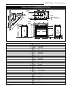
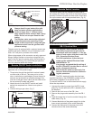
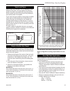
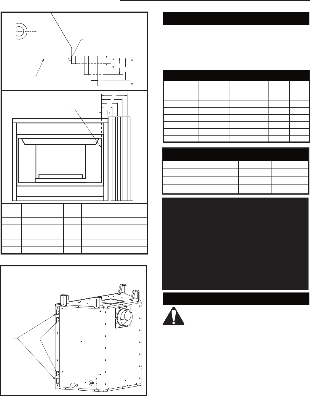
Mantel
Leg
CFM164a
Mantel Leg Chart
06/22/01 sta
CFM170
DV Builder Front
View
O
N
M
L
K
Black
Surround
Face
CFM164a
Side of
Combustion Chamber
CFM170
Mantel Mantel Leg from Side
Ref. Leg Depth Ref. of Comb. Opening
F 10” (254 mm) K 11¹⁄₂” (292 mm)
G 8” (203 mm) L 9¹⁄₂” (241 mm)
H 6” (152 mm) M 7¹⁄₂” (191 mm)
I 4” (101 mm) N 5¹⁄₂” (140 mm)
J 2” (51 mm) O 3¹⁄₂” (89 mm)
Fig. 4b Combustible mantel leg minimum installation.
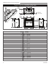
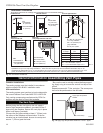
A
B
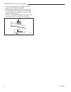
Flange Drywall
Position Depth
A 1/2” / 13 mm
B 5/8” / 16 mm
Flange Location for
Desired Drywall Depth
FP1539
Fig. 5 Drywall flange location.
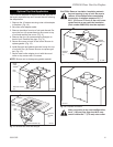
Final Finishing
Noncombustible materials such as brick or tile can be
extended over the edges of the face of the fireplace.
Do not cover the window frame assembly, any vent,
louvre assembly top or louvre assembly bottom. If
a Trim Kit is to be installed, brick and tile will have to be
installed flush with the side of this appliance.
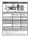
Gas Specifications
Max. Min.
Gas Input Input
Model Fuel Control BTU/h BTU/h
DVB4136RN Natural Gas Millivolt Hi/Lo 30,000 18,500
DVB4136RP Propane Millivolt Hi/Lo 30,000 17,000
DVB4136IN Natural Gas 24 Volt Hi/Lo 30,000 21,800
DVB4136IP Propane 24 Volt Hi/Lo 30,000 21,300
DVB4136RFN Natural Gas Comfort Control 30,000 21,000
DVB4136RFP Propane Comfort Control 30,000 23,500
Gas Inlet and Manifold Pressures
Natural LP (Propane)
Minimum Inlet Pressure 5.5” w.c. 11.0” w.c.
Maximum Inlet Pressure 14.0” w.c. 14.0” w.c.
Manifold Pressure 3.5” w.c. 10.0” w.c.
High Elevations
Input ratings are shown in BTU per hour and are
certified without deration for elevations up to
4,500 feet (1,370m) above sea level.
For elevations above 4,500 feet (1,370m) in USA,
installations must be in accordance with the
current ANSI Z223.1/NFPA 54 and/or local codes
having jurisdiction.
In Canada, please consult provincial and/or local
authorities having jurisdiction for installations at
elevations above 4,500 feet (1,370m).
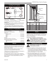
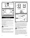
Gas Line Installation
When purging gas line the front glass
must be removed.
The gas pipeline can be brought in through the right
side of the appliance. Knockouts are provided at conve-
nient locations to allow for the gas pipe installation and
testing of any gas connection.
The gas line connection can be made with properly
tinned 3/8” copper tubing, 1/2” rigid pipe or an approved
flex connector. Since some municipalities have addi-
tional local codes, it is always best to consult your local
authority and the CSA-B149.1 installation codes.
For USA installations consult the current National Fuel
Gas Code, ANSI Z223.1/NFPA 54.
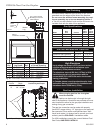
3/4” (19 mm) Scribe
Moulding for use with
CFM Cabinets