44
10 Start-up
Start the water heater
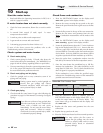
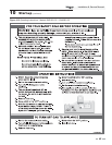
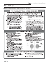
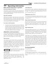
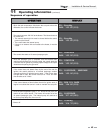
1. Read and follow the Operating instructions in FIG.’s 10-2
and 10-3, pages 45 and 46.
If water heater does not start correctly
1. Check for loose connections, blown fuse or service switch
off.
2. Is external limit control (if used) open? Is water
temperature above 200°F?
3. Is tank set point set below tank temperature?
4. Is gas turned on at meter and water heater?
5. Is incoming gas pressure less than 4 inches w.c.?
If none of the above corrects the problem, refer to the
Troubleshooting section of this manual.
Check system and water heater
Check water piping
1. Check system piping for leaks. If found, shut down the
water heater and repair immediately. (See WARNINGS on
pages 43 and 44 (startup) regarding failure to repair leaks.)
2. Vent any remaining air from the system using manual vents.
Air in the system will interfere with circulation and cause
hot water distribution problems and noise.
Check vent piping and air piping
1. Check for gastight seal at every connection, seam of air
piping, and vent piping.
Venting system must be sealed gastight to
prevent flue gas spillage and carbon
monoxide emissions, which will result in
severe personal injury or death.
Check gas piping
1. Check around the water heater for gas odor following the
procedure on page 35 of this manual (Connecting Gas Supply
Piping).
If you discover evidence of any gas leak, shut
down the water heater at once. Find the leak
source with a bubble test and repair
immediately. Do not start the water heater
again until corrected. Failure to comply
could result in severe personal injury, death,
or substantial property damage.
Check flame and combustion
1. Press the SHUTDOWN button on the display until
HTR:Off appears in the display window.
2. Remove the screws securing the top panel to the unit.
Remove the panel from the unit to gain access to the flue
sensor.
3. Locate the flue sensor in the top of the vent connection.
Remove the flue sensor and grommet from the unit.
Note:
Combustion measurements will be made at this
point.
4. Press the SHUTDOWN button on the display until
HTR:Standby appears in the display window.
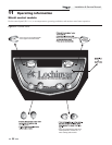
5. Locate the pinhole button above the “r” in the Lochinvar
logo on the display board (FIG. 11-1). Insert a thin wire
(such as a paper clip) into the hole and press the button
once and hold for 5 seconds to place the water heater into
Service Mode. In Service Mode the water heater will fire
at ignition speed and will then modulate up to full fire.
6. Insert the probe from a combustion analyzer into the
hole left by the removal of the flue temperature sensor.
7. Once the water heater has modulated up to full fire,
measure the combustion. The values should be in the
range listed in Table 10A. The CO levels should be less
than 150 ppm for a properly installed unit.
If the combustion is not within the specified range,
reference the Troubleshooting section of this manual for
possible causes and corrective actions.
ƽ WARNING
ƽ WARNING
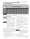
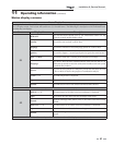
Table 10A Flue Products Chart
8. Once the combustion analysis is complete, press the
SHUTDOWN button on the display board (FIG. 11-1)
to take the water heater out of Service Mode. The
water heater will go to shutdown and the display will
show HTR:Off.
9. Replace the flue sensor and grommet into the vent
connection.
10. Replace the top panel on the unit.
11. Place the Shield water heater back into normal operation.
You must replace the flue sensor to
prevent flue gas spillage into the room.
Failure to comply could result in severe
personal injury, death, or substantial
property damage.
ƽ WARNING
Natural Gas Propane
CO
2
O
2
CO
2
O
2
8.0% - 10% 3.0% - 6.5% 9.0% - 11% 4.1% - 6.9%
Installation & Service Manual
TM


