39
8 Field wiring
ELECTRICAL SHOCK HAZARD – For
your safety, turn off electrical power
supply before making any electrical
connections to avoid possible electric
shock hazard. Failure to do so can cause
severe personal injury or death.
Wiring must be N.E.C. Class 1.
If original wiring as supplied with the
water heater must be replaced, use only
type 105°C wire or equivalent.
The water heater must be electrically
grounded as required by National
Electrical Code ANSI/NFPA 70 – latest
edition.
Installation must comply with:
1. National Electrical Code and any other national, state,
provincial, or local codes, or regulations.
2. In Canada, CSA C22.1 Canadian Electrical Code Part 1, and
any local codes.
Power cord connection
This water heater is designed to operate with 120 VAC and 60 Hz
power supply. If allowed by local codes, connect the power cord
provided with the heater to a GFI protected outlet on a separate
circuit and breaker. Ensure the circuit cannot be interrupted by
a switch used to control lights or other appliances.
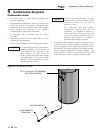
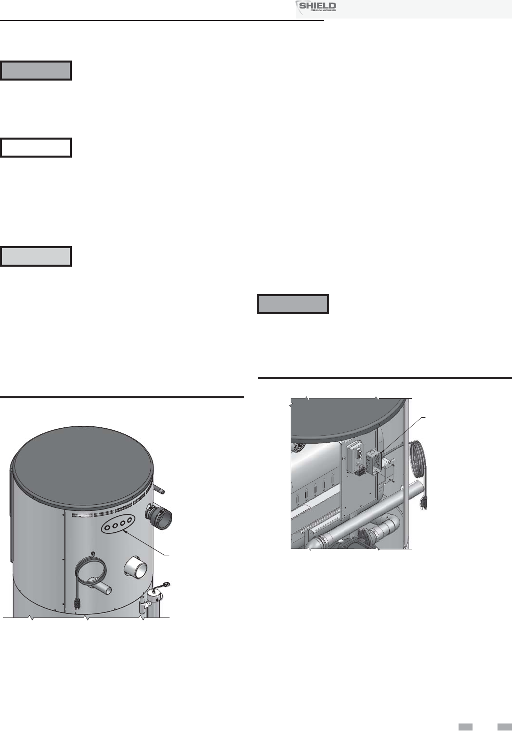
If local codes do not allow for the use of the power cord, remove
the cord from the junction box found on the side of the control
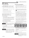
support bracket (FIG. 8-2) and attach conduit to the junction
box. Route the wires out of the appliance to a GFI protected
outlet on a separate circuit and breaker.
Label all wires prior to disconnection
when servicing controls. Wiring errors
can cause improper and dangerous
operation.
ƽ WARNING
NOTICE
ƽ CAUTION
LOW VOLTAGE
WIRING KNOCKOUTS
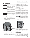
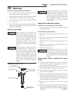
Figure 8-1 Routing Field Wiring
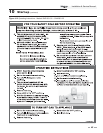
Auxiliary device proving switch
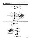
1. When the operation of an external limit needs to be
verified before the water heater fires, remove the jumper
wire from terminals X & B and connect them to the
contacts on the external limit (FIG. 8-3).
Low voltage connections
1. Route all low voltage wires through the knockouts in the
rear of the water heater, as shown in FIG. 8-1.
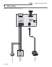
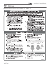
2. Connect low voltage wiring to low voltage connection
board as shown in FIG. 8-3 on page 40 of this manual and
the water heater wiring diagram.
Runtime contacts
The electronic control closes a set of dry contacts whenever the
burner is running. This is typically used by Building
Management Systems to verify that the water heater is
responding to a call for heat.
Alarm contacts
The electronic control closes another set of contacts whenever
the water heater is locked out or the power is turned off. This
can be used to turn on an alarm, or signal a Building
Management System that the water heater is down. Note that
the alarm contacts will close momentarily after each call for
heat.
Installation & Service Manual
TM
JUNCTION BOX
Figure 8-2 Remove Power Cable
Use of an extension cord is NOT allowed. If
a suitable electrical outlet is not within reach
of the supplied power cord, a new receptacle
must be installed or the power cord must be
replaced with hard conduit as described
above.
ƽ WARNING


