


Installation & Operation Manual
48
6 Start-up
Check thermostat circuit(s)
1. Disconnect the two external wires connected to the enable
terminals on the connection board.
2. Connect a voltmeter across these two incoming wires.
Close each thermostat, zone valve, and relay in the external
circuit one at a time and check the voltmeter reading across
the incoming wires.
3. There should NEVER be a voltage reading.
4. If a voltage does occur under any condition, check and
correct the external wiring. (This is a common problem
when using 3-wire zone valves.)
5. Once the external thermostat circuit wiring is checked and
corrected if necessary, reconnect the external thermostat
circuit wires to the connection board. Allow the boiler to
cycle.
Check vent and air piping
Inspect vent piping and air piping for signs of deterioration
from corrosion, physical damage or sagging. Verify air piping
and vent piping are intact and correctly installed per this
manual.
Placing the boiler in operation
Boiler operational checks
1. Turn the boiler main power switch to the “ON”
position.
2. Verify operation of the SMART SYSTEM control
module and Operator Interface.
3. Program the adjustable points from the Operator
Interface.
4. Push the reset for the low water cutoff (if equipped).
5. Ensure that maximum flow to the boiler does not exceed
55 GPM on Models 402 - 752 and 90 GPM on Models
992 - 2072. Verify by checking temperature rise while
burner is firing at 100% of rated input.
6. Install a manometer on the gas supply to the boiler and
verify minimum gas supply pressure as the burner fires at
100% of rated input.
7. Verify operation of safeties as necessary (low water
cutoff, high limit, gas pressure, etc.,).
8. Verify that all adjustable points in the Operator
Interface are set as required.
9. Once the boiler analysis is complete, test the safety shutoff
device by turning the manual shutoff valve to the OFF
position and ensuring that the boiler shuts down and
registers an alarm. Open the manual shutoff valve and reset
the control.
10. Place the boiler back into normal operation.
Boiler operation
11. Boiler should begin the start-up process for the
sequence of operation.
12. The boiler will ignite at the proper ignition speed and
will stage to meet the system demand.
13. Ensure that inlet water temperature does not fall below
the specified minimum for the boiler.
14. Based on system demand, boilers may run for an
extended period of time at a reduced rate of input to
maximize efficiency.
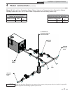
Start the boiler
Read and follow the Lighting Instructions in FIG. 6-1, on page
49.
If boiler does not start correctly
1. Check for loose connections, blown fuse or service switch
off?
2. Is external limit control (if used) open? Is boiler water
temperature above 200°F (93.3°C)?
3. Is thermostat set below room temperature?
4. Is gas turned on at meter or boiler?
5. Is incoming gas pressure less than 4.5" water column?
If none of the above corrects the problem, refer to the
Troubleshooting Section of the Copper-fin II Service Manual.
The venting system must be installed so that
it will prevent flue gas spillage and carbon
monoxide emissions, which will result in
severe personal injury or death.
ƽ WARNING
Set space heating operation (boiler only)
Determine controlling sensor
For space heating systems, the temperature control can be based
on one of four sensors; the inlet, outlet, system supply sensor,
or system return sensor. The SMART SYSTEM control is
programmed at the factory to control the temperature of the
outlet sensor. The control will automatically switch to the
system supply sensor once it is connected. If it is desired to base
the temperature control on the inlet sensor, the appropriate
parameter must be changed in the control. See the Copper-fin II
Service Manual for a detailed explanation of this procedure. The
control will automatically switch to the system return sensor
once it is connected. It is recommended that a system supply
sensor be installed even when using the inlet sensor as the
controlling sensor.
Verify space heat circulator mode
The Space Heating Mode controls both the system (primary)
pump (if connected), and the boiler (secondary) pump. When
the SMART SYSTEM control receives a space heating call for
heat, it turns on the system pump. If the boiler is not heating
an indirect DHW (Domestic Hot Water) tank, it also turns on
the boiler pump. After the space heating call for heat ends, the
system pump continues to run for a short period of time. If the
boiler pump was running, it continues to run for a short period
of time as well. These pump delays are factory set to 30 seconds.
If different delays are desired, the appropriate parameters in the
control must be changed. See the Copper-fin II Service Manual
for a detailed explanation of this procedure.
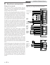
Set space heating set point temperature
The UP and DOWN keys may be used during normal operation
to adjust the space heating set point temperature (see FIG. 7-1
on page 56 of this manual). Once the desired temperature is
displayed, press the ENTER/RESET key to save the new setting.
If the ENTER/RESET key is not pressed, the new setting will
be used for the current heating cycle only. The old setting will
become active after the current heating cycle ends.
15. As system demand is satisfied, the burner will cycle off
and the combustion air blower will run for a post
purge operation before the boiler shuts down.