


Installation & Operation Manual
46
5 Electrical connections
ALARM
S
T
A
G
I
N
G
C
A
S
C
A
D
E
M
O
D
B
U
S
CN3
CN2
RUN-TIME
CONTACTS
OPEN
CLOSE
COM
S1
S2
S2
S3
S3
S4
S4
LOUVER
RELAY COIL
LOUVER
PROVING SW
CONTACTS
S1
AQUASTAT
TANK
TANK
SENSOR
SHIELD
A
B
SHIELD
+ 0-10V
- BMS IN
+ 0-10V
- RATE OUT
SHIELD
A
B
SHIELD
35
34
33
32
31
30
29
28
27
26
25
24
23
22
21
20
19
18
17
16
15
14
13
12
11
10
9
8
7
6
5
4
3
2
1
3
-
W
A
Y
V
A
L
V
E
B
TO MONITORING DEVICE
OUTDOOR
SENSOR
SYS SUPPLY
SYS RETURN
+ 0-10V SYS
SENSOR
SENSOR
- PUMP IN
CN2
TO MONITORING DEVICE
THREE WAY
VALVE
LOUVER
PROVING
SWITCH
DHW TANK
THERMOSTAT
LINE
TO LOUVER
10K-TANK
SENSOR
A
B
A
FROM
PREVIOUS
HEATER
TO NEXT
HEATER
EXTERNAL
SEQUENCER/
BUILDING
AUTOMATIC
CONTROL
SYSTEM SUPPLY
SENSOR
SYSTEM RETURN
SENSOR
OUTDOOR
AIR SENSOR
(BOILER ONLY)
PUMP SPEED
INPUT
0-10VDC
COMMON
S1
S2
S3
S4
EXTERNAL
STAGING
SEQUENCER
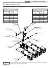
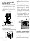
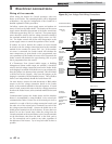
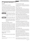
Figure 5-4_Low Voltage Field Wiring Connections
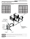
Wiring of the cascade
When wiring the heaters for Cascade operation, select one
heater as the Leader. The remaining heaters will be designated
as Members. See page 50 Configuration of the Cascade for a
detailed explanation of this procedure.
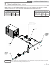
On boilers, connect the system supply sensor and outdoor air
sensor (if used) to the Leader boiler. The location of the system
supply sensor should be downstream of the boiler connections
in the main system loop (FIG.’s 4-3 and 4-6). The system supply
sensor should be wired to the low voltage connection board at
the terminals marked for the system supply sensor (see FIG.
5-4). The Leader control will use the water temperature at the
system supply sensor to control the operation of the Cascade.
If outdoor air reset is desired, the outdoor air sensor should
be wired to the low voltage connection board at the terminals
marked for the outdoor air sensor (FIG. 5-4). If the outdoor
air sensor is connected, the Leader control will calculate the
water temperature set point based on the programmed reset
curve parameters. If the outdoor air sensor is not connected, the
Leader control will maintain the space heating (SH) set point
that is programmed into the control.
If a Thermostat, Zone Control enable output, or Building
Management System enable output are available, it should be
wired to the low voltage connection board on the Leader boiler
at the Staging S1 terminals. If the boilers are to run continuously,
leave the jumper wire between these terminals. This will initiate
a call for heat on the Cascade. Also, leave the jumpers on the
Staging S1 terminals of all the Member heaters. This will allow
them to run independently should the Leader heater fail.
On water heaters, connect the tank thermostat or BMS enable
output to the low voltage connection board on the Leader
heater, at the terminals marked for the tank Aquastat. If a tank
sensor is used, connect this sensor to the low voltage connection
board on the Leader heater, at the terminals marked for the tank
sensor.
Communication between the Leader heater and the Member
heaters is accomplished by using shielded, 2-wire twisted pair
communication cable. Connect one of the twisted pair wires to
terminal A on each of the low voltage connection boards, and
the other wire of the twisted pair to terminal B on each of the
low voltage connection boards. Connect the shield wire to the
shield ground terminal on all of the heaters. If more than two
heaters are on the Cascade, daisy chain the wiring from the
Cascade terminals on the second heater to the Cascade terminals
on the third heater, then from the third to the forth, and so
on. The connections can be made in any order, regardless of
the addresses of the heaters. Try to keep each cable as short as
possible.