


Installation & Operation Manual
37
ƽ CAUTION
A boiler allowed to operate at set point
temperatures below the specified minimum
settings may experience operational
problems with the operating controls
and safety switches, obstruction of the
flue gas passages on the heat exchanger,
incomplete combustion and possible flue gas
spillage. Operation at lower than specified
water temperatures may cause hazardous
conditions that result in non-warrantable
damage to the appliance.
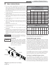
Three way valves in system
The installation of a three way valve on this boiler is not
generally recommended because most piping methods allow
the three way valve to vary flow to the boiler. This boiler is a
low mass, high efficiency appliance which requires a constant
water flow rate for proper operation. Low flow rates can
result in overheating of the boiler water which can cause
short burner cycles, system noise, relief valve discharge and in
extreme cases, a knocking flash to steam. These conditions
can cause operational problems and non-warrantable failures
of the boiler.
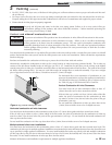
Radiant floor and snow melt heating
systems
This type of heating boiler application operates in a low
temperature range which requires a boiler bypass as described
under the Low Temperature Bypass Requirements section. A
non-metallic rubber or plastic tubing installed in a radiant (in
floor) system must have an oxygen barrier to prevent oxygen
from entering the system through the walls of the installed
tubing. Excessive oxygen absorption into the system will result
in an accelerated rate of corrosion causing a sludge buildup.
This excessive corrosion will also damage the boiler and system
components. Sludge formed as the result of excessive oxygen
in the system can restrict water flow resulting in a premature
boiler failure. Any boiler damage due to excessive oxygenation
is non-warrantable.
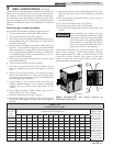
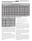
TABLE - 4B
MAXIMUM FLOW FOR HEATING BOILER
The maximum flow rate through the boiler with a copper
heat exchanger must not exceed the following:
Model Maximum Flow
402, 502, 652, and 752 55 GPM
992, 1262, 1442, 1802, and 2072 90 GPM
If higher flow rates are required through the boiler, an optional
Cupro-Nickel heat exchanger is available. Consult the factory
for specific application requirements.
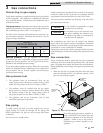
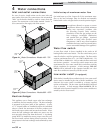
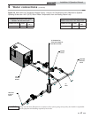
4 Water connections (continued)
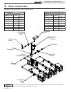
When a mixing valve is used, an optional system return sensor
should be installed into the system return piping. This will allow
the display of the actual system return temperature, and will
also allow control of the system return temperature when the
SMART SYSTEM control is programmed for inlet temperature
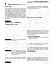
control. As always, installation of the system supply sensor is
strongly recommended as well. This will reduce the potential
for short cycling of the boiler, and provide more responsive
temperature regulation, even when the SMART SYSTEM
control is programmed for inlet temperature control.
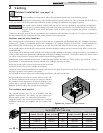
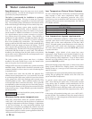
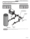
Low system water volume
System run time is very important to the overall operating
efficiency of the boiler. Short cycling of the boiler creates
problems with condensation in the vent stack, condensation on
the heat exchanger, system temperature spikes, and mechanical
component failures. To prevent short cycling of the boiler, it
is important to limit the boiler cycles to six or fewer per hour.
A buffer tank is an effective way to enhance a small system load
and increase heating system efficiency (see FIG. 4-6 on page 42
of this manual). Buffer tanks add water volume to the system
and act as a flywheel to absorb the additional Btu’s provided by
the boiler when only a single zone of a large system is calling
for heat.
To calculate the proper buffer tank size for a multiple zone
system:
(Run Cycle) (Output - Minimum System Load)
(Temp. Rise) (8.33) (60 Min.)
CFN2072
Min. Load = 100,000 Btu/Hr
Min. Boiler Output = 850,000 Btu/Hr
Cycle Time = 10 Min
Temp. Rise = 38
(10)(850,000 – 100,000) / (38)(8.33)(60) = 395 Gallons