


42
Installation & Operation Manual
4 Water connections
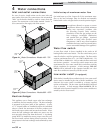
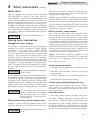
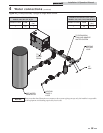
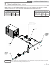
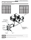
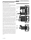
Figure 4-6_Primary/Secondary Piping with Buffer Tank
1" TEMPERATURE
AND PRESSURE
GAUGE
AUTOMATIC AIR
ELIMINATOR/VENT
SYSTEM
OUTLET
SYSTEM
SENSOR
LOCATION
SYSTEM
INLET
BUFFER
TANK
DRAIN
PUMP
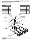
COMMOM MANIFOLD
MUST BE SIZED TO
ACCOMODATE COMBINED
FLOW RATE FOR
ALL BOILERS
NOTICE
The Inlet/Outlet System tappings are shown in the optional location on the side of the tank for pictorial purposes.
The standard location for the system tappings is 180° from the recirculation tappings.
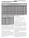
COMMON MANIFOLD SIZE (Min.)
Models: 402, 502, 652, & 752
Number of Units GPM
Diameter
(in.)
2 110 3
3 165 3 1/2
4 220 4
5 275 5
6 330 5
7 385 6
8 440 6
COMMON MANIFOLD SIZE (Min.)
Models: 992, 1262, 1442, 1802 & 2072
Number of Units GPM
Diameter
(in.)
2 180 4
3 270 5
4 360 6
5 450 6
6 540 6
7 630 7
8 720 7
Please note that these illustrations are meant to show system piping concept only, the installer is responsible for
all equipment and detailing required by local codes.
NOTICE