


38
Installation & Service Manual
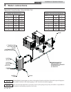
4 Water connections
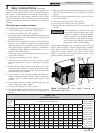
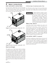
The installer must ensure that the boiler is supplied with adequate
flow without excessive temperature rise. It is recommended
that this boiler be installed with a bypass in the piping if the
maximum recommended flow rate is exceeded. The bypass will
help to ensure that the boiler can be supplied with adequate
water flow. Flow rates exceeding the maximum recommended
flow will result in erosion of the boiler tubes. A typical bypass
with a valve as shown in FIG. 4-5 will allow control of boiler
flow.
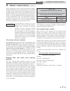
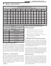
TABLE - 4D
BOILER TEMPERATURE RISE AT MAXIMUM FLOW
Temperature Rise at Full Rate Fire, 55 and 90 GPM
Maximum Flow
Model Temperature Rise °F
402 12 @ 55 GPM
502 15 @ 55 GPM
652 20 @ 55 GPM
752 23 @ 55 GPM
992 19 @ 90 GPM
1262 24 @ 90 GPM
1442 27 @ 90 GPM
1802 34 @ 90 GPM
2072 39 @ 90 GPM
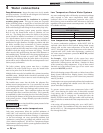
Boiler bypass requirements
TABLE - 4C
SYSTEM TEMPERATURE RISE CHART
Temperature Rise and Head Loss Based on Boiler Output in Btu/hr
Btu/hr 30°F T 35°F T 40°F T 45°F T 50°F T 55°F T 60°F T
Input Output GPM Ft/hd GPM Ft/hd GPM Ft/hd GPM Ft/hd GPM Ft/hd GPM Ft/hd GPM Ft/hd
399,999 339,999 23 1.1 19 0.7 -- -- -- -- -- -- -- -- -- --
500,000 425,000 28 1.6 24 1.2 21 0.7 19 0.7 -- -- -- -- -- --
650,000 552,500 37 3.0 31 2.2 28 1.6 24 1.2 22 0.9 20 0.7 18 0.6
750,000 637,500 42 4.1 36 2.8 32 2.3 28 1.6 25 1.3 23 1.1 21 0.7
990,000 841,500 55 2.6 48 2.3 42 1.5 37 1.4 33 1.0 30 0.9 28 0.9
1,260,000 1,071,000 71 4.4 61 3.6 53 2.7 48 2.3 42 1.7 39 1.5 35 1.2
1,440,000 1,224,000 81 6.3 70 5.0 61 3.8 54 2.7 48 2.3 44 2.0 40 1.8
1,800,000 1,530,000 102* 11.8 87 9.0 76 6.6 68 5.6 61 4.4 55 2.6 50 3.0
2,070,000 1,759,500 -- -- 100* 10.1 87 9.0 78 7.6 70 6.2 64 5.4 58 4.6
*Cupro-Nickel Heat Exchanger Required at Flows Above 55 GPM on Models 402 - 752 and above 90 GPM on Models 992 - 2072.
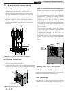
Temperature / pressure gauge
This boiler is equipped with a dial type temperature / pressure
gauge. This gauge is factory installed in the outlet side of the
boiler piping. The gauge has one scale to read system pressure
and a separate scale to read water temperature in degrees
Fahrenheit. The temperature / pressure gauge is provided to
meet code requirements. Water temperatures can be more
accurately monitored from the data provided in the digital
display in the Operator Interface.
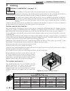
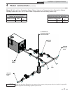
Typical heating boiler installations
General plumbing rules:
1. Check all local codes.
2. For serviceability of boiler, always install unions.
3. Always pipe pressure relief valve to an open drain.
4. Locate system air vents at highest point of system.
5. Expansion tank must be installed near the boiler and
on the suction side of the system pump.
6. Support all water piping.
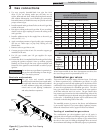
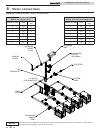
Installation with a chilled water system
Pipe refrigeration systems in parallel. Install duct coil
downstream at cooling coil. Where the hot water heating
boiler is connected to a heating coil located in the air handling
units which may be exposed to refrigeration air circulation, the
boiler piping system must be equipped with flow control valves
or other automatic means to prevent gravity circulation of the
boiler water during the cooling cycle.
The coil must be vented at the high point and hot water from the
boiler must enter the coil at this point. Due to the fast heating
capacity of the boiler, it is not necessary to provide a ductstat to
delay circulator operation. Also, omit thermostat flow checks
as the boiler is cold when heating thermostat is satisfied. This
provides greater economy over maintaining standby heat.
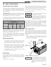
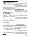
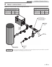
DHW installation
Boilers may be utilized with a Hot Water Generator tank
for domestic hot water. When used for DHW, either a tank
thermostat or sensor must be installed in a bulbwell within the
tank and connected back to the unit in order for the controller
to regulate water temperature and a pump for DHW. Pumps
used for DHW purposes should be sized to provide adequate
flow to the boiler when in DHW Mode. Reference FIG. 4-3
shown with a Hot Water Generator for DHW on page 39 for a
typical DHW piping scheme.