


34
Installation & Service Manual
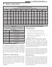
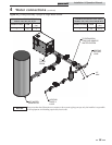
4 Water connections
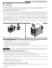
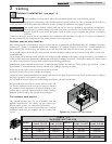
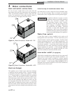
Figure 4-1_Water Connections - Models 402 - 752
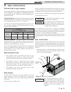
Heat exchanger
This appliance uses a finned copper tube heat exchanger
to maximize the heat transfer process. The heat exchanger
is mounted in the inner jacket of the appliance. A series
of “V” shaped baffles are installed between the individual
tubes to control the movement of the flue products over
the finned copper surface and increase heat transfer. Water
enters the heat exchanger and makes two passes over the
area exposed to direct heat from the burner. A circulating
pump MUST be installed to ensure proper water flow over
the heat transfer surfaces during burner operation. Water
temperatures in the heat exchanger are determined by water
flow.
ƽ CAUTION
An appliance allowed to operate at return
temperatures below the specified minimum
setting may experience problems with
the operating controls, safety switches,
obstruction of the flue gas passages on the
heat exchanger, incomplete combustion
and possible flue gas spillage. Sustained
operation at lower than specified water
temperatures (140°F) may cause hazardous
conditions that may result in personal injury
or non-warrantable damage to the appliance.
Inlet and outlet connections
For ease of service, install unions on the water inlet and
water outlet of the unit. The connection to the unit marked
“Inlet” on the header should be used for return from the
system. The connection on the header marked “Outlet” is
to be connected to the supply side of the system.
2" NPT
WATER
INLET
2" NPT
WATER
OUTLET
INSPECTION
PLUGS
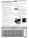
Water flow switch
A water flow switch is factory installed in the outlet on all
heating boilers and water heaters. The flow switch must prove
water flow before a trial for ignition can begin. The flow switch
requires a minimum flow of 15 - 18 GPM on Models 402 - 752
and 26 GPM on Models 992 - 2072 to make the flow switch and
start burner operation. A water flow switch meets most code
requirements for a low water cutoff device on boilers requiring
forced circulation for operation. A fault message, Flow Sw/
LWCO will be indicated in the Operator Interface on a low
water flow condition as sensed by the flow switch.
Low water cutoff (if equipped)
If this boiler is installed above radiation level, a low water cutoff
device must be installed at the time of boiler installation. An
electronic low water cutoff is available as a factory supplied
option on all models. The low water cutoff should be inspected
every 6 months. A fault message, Flow Sw/LWCO will be
indicated in the Operator Interface on a low water condition as
sensed by the low water cutoff.
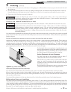
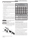
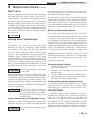
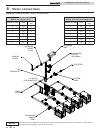
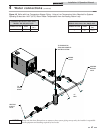
Figure 4-2_Water Connections - Models 992 - 2072
2-1/2" NPT
WATER
INLET
2-1/2" NPT
WATER
OUTLET
INSPECTION
PLUGS
Initial set-up of maximum water flow
On initial start-up of the Copper-fin II, the maximum water
flow to the heat exchanger must be checked and manually
limited with a valve or bypass before normal operation begins.