


51
Installation & Operation Manual
10 Operating information (continued)
Monitor external limits
Connections are provided on the connection board for
external limits such as flow switch and a louver proving
switch. The SMART TOUCH control will shut off the
burner and inhibit relighting whenever any of these external
limits open.
Run-time and alarm outputs
The boiler provides dry contacts for indicating when the
boiler is running, and when it is unable to operate.
Run-time and cycle counting
The control uses two timers to monitor the total hours of
burner operation. One timer monitors the time the boiler
is firing under 50% of rate. The other timer monitors the
time the boiler is firing over 50% rate.
The control uses four (4) ignition counters to monitor the
amount of boiler cycles. The first counter counts all
ignitions of the control. The second counter counts only
ignition attempts that have failed. The third and fourth
counters are the same as the first and second respectively,
but can be reset by the installer.
Service reminder
The control can be programmed for service reminder
notification. This notification will become active when
either a set time frame has expired, or a set amount of
running hours or cycles has expired (all adjustable by the
installer). The display will alternate the standard text on the
display screen with Service Due every 5 seconds. The
service reminder notification can be reset by the installer.
Error logging
The control will hold in memory the last 10 error codes as
well as the last 10 turn-off functions. The date and time of
the occurrence will be recorded as well. Only the 10 most
current occurrences will be held in memory.
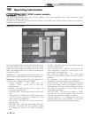
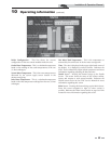
Boiler temperature regulation
Operating temperature (target)
The SMART TOUCH control module senses water
temperature and regulates boiler firing and firing rate to
achieve a target temperature. The target temperature can be
set between 70°F (21°C) and 190°F (88°C).
• Target temperature is fixed when the outdoor
sensor is not installed.
• Target temperature is calculated as described below
under “Outdoor Reset Operation” and “Target
Temperature Boost” when the outdoor sensor is
connected.
High limit operations
When outlet temperature exceeds 200°F (93.3°C), high limit
action occurs. The boiler shuts down until the outlet water
cools down.
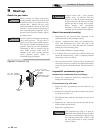
Low water cutoff protection
1. A low water cutoff device with test and reset functionality is
provided in the boiler as standard equipment.
Flow sensing device
1. The SMART TOUCH control module uses temperature
sensing of both supply and return temperatures of the heat
exchanger. If the flow rate is too low or the outlet
temperatures too high, the control module modulates
down and will shut the boiler off. This ensures boiler
shutdown in the event of low flow conditions.
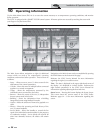
Outdoor reset operation, if used
Target temperature with outdoor reset
This feature improves the system’s efficiency as the outdoor
temperature warms up.
See the SYNC Service Manual to change the settings.
Reset curve
The reset curve looks at outdoor air temperature and adjusts the
set point.
Cascade
When multiple boilers are installed, they can be wired together
in a cascade sequence. A maximum of eight boilers can be
controlled from a single control. In this application one boiler
would be designated as the Leader control and all others would
be designated as Member controls.
Once the Leader boiler receives a call for heat from the Enable
input or 0 - 10 VDC input, the control will determine what the
set point will be. If outdoor air reset is desired, connect the
outdoor air sensor to the terminals on the Low Voltage
Connection Board on the Leader boiler. The set point will be
calculated based on the programmed reset curve parameters.
See the SYNC Service Manual to program the reset curve. If
outdoor air reset is not desired, do not connect the outdoor air
sensor. A fixed temperature set point can be programmed into
the control.
NOTICE
If a mechanical flow switch is required to
meet local code requirements the SYNC
boiler can be equipped with field supplied
switches on each inlet. Please reference page
39 of this manual for more information.