


32
Installation & Operation Manual
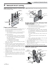
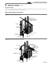
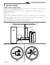
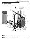
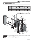
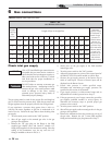
5 Hydronic piping
HOT WATER
GENERATOR
SYSTEM
CIRCULATOR
AIR
SEPERATOR
MAKE UP
WATER
DRAIN POINT
(TYPICAL)
SYSTEM SUPPLY
SENSOR
BALL VALVE
(TYPICAL)
HEAT EXCHANGER 2
BOILER PUMP
PRESSURE RELIEF
VALVE
FLOW CHECK
VALVE (TYPICAL)
PRESSURE REDUCING
(VALVE)
EXPANSION
TANK
UNION (TYPICAL)
TEMPERATURE/
PRESSURE GAUGE
WATER GENERATOR
CIRCULATOR
(TYPICAL)
BACK FLOW
PREVENTER
PRESSURE GAUGE
HEAT EXCHANGER 1
BOILER PUMP
Y-STRAINER
(RECOMMEND)
(TYPICAL)
MAY SUBSTITUTE LOW LOSS HEADER
T
O
S
Y
S
T
E
M
TO FLOOR
DRAIN
F
R
O
M
S
Y
S
T
E
M
Figure 5-5 Single Boiler - Primary/Secondary Piping
NOTICE
System flow should always remain higher than the required flow for the boiler(s) when the boiler(s) is in
operation to prevent short cycling and high limit issues.
NOTICE
A system supply sensor (factory
supplied) MUST BE installed for proper
boiler operation.
Please note that these illustrations are meant to show system piping concept only, the installer is responsible
for all equipment and detailing required by local codes.
NOTICE