


Installation & Operation Manual
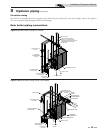
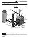
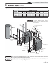
It is required that near boiler piping systems
utilize Primary/Secondary configurations as
shown in FIG.’s 5-5 and 5-6 only. The use of
other near boiler piping configurations
could result in improper building and
system flow rates leading to inadvertent
boiler high limit shutdowns and poor system
performance.
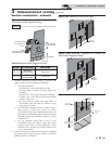
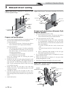
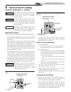
Near boiler piping components
1. Boiler piping:
Boiler system piping MUST be sized per the pipe
requirements listed in Table 5A. Reducing the pipe size
can restrict the flow rate through the boiler, causing
inadvertent high limit shutdowns and poor system
performance.
2. Boiler circulating pump:
Field supplied. The boiler circulating pump MUST be
sized to meet the specified minimum flow requirements
listed in FIG. 5-4.
3. Hot Water Generator circulating pump:
Field supplied. The pump MUST be sized to meet
the specified minimum flow requirements listed in
FIG. 5-4. Consult the indirect boiler operating
guide to determine flow characteristics for the selected
product used.
4. Boiler isolation valves:
Field supplied. Full port ball valves are required. Failure
to use full port ball valves could result in a restricted flow
rate through the boiler.
5. Check valves:
Field supplied. Check valves are required for
installation as shown in FIG.’s 5-5 and 5-6. Failure to
install check valves could result in a reverse flow condition
during pump(s) off cycle.
6. Domestic indirect hot water isolation valves:
Field supplied. Full port ball valves are
required. Failure to use full port ball valves could
result in a restricted flow rate through the boiler.
7. Anti-scald mixing valve:
Field supplied. An anti-scald mixing valve is
recommended when storing domestic hot water above
115°F (46°C).
8. Unions:
Field supplied. Recommended for unit serviceability.
9. Pressure relief valve:
Factory supplied. The pressure relief valve is sized to
ASME specifications.
10. System temperature sensor:
Lochinvar supplies a system temperature sensor.
The sensor is to be installed in the heating loop
downstream from the boiler hot water piping and
heating loop junction. The sensor should be
located far enough downstream to sense system diluted
water temperature.
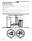
NOTICE
Pump sizing and flow requirements are
based on 20 feet (6 m) of black iron piping,
4 - 90° elbows, and 2 - fully ported ball
valves.
*When using copper with a 20° temperature
rise increase piping to 3".
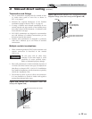
NOTICE
5 Hydronic piping (continued)
NOTICE
A system supply sensor (factory supplied)
MUST BE installed for proper boiler
operation.
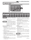
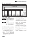
TEMPERATURE RISE APPLICATIONS
Model
MINIMUM PIPE
SIZE
20°F 25°F 30°F 35°F
GPM FT/HD GPM FT/HD GPM FT/HD GPM FT/HD
1000 2½" 55 31 44 22 38 18 32 13
1300 2½" 65* 30 52 20 45 16 37 11
1500 2½" 74* 33 60 23 51 18 42 12
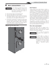
0
10
20
30
40
50
60
0 102030405060708090
SB1500
SB1300
SB1000
Pressure Drop vs Flow
Flow Rate (GPM) - Single Heat Exchanger Only
Pressure Drop (Feet of Head)
Single Heat Exchanger Only
Figure 5-4 Pressure Drop vs. Flow
Table 5A Sizing Information for Temperature Rise Applications_20°F, 25°F, 30°F and 35°F
11. Y-Strainer:
Field supplied. A Y-strainer or equivalent multipurpose
strainer is recommended at the inlet of the heat exchanger
to remove system particles from older hydronic systems and
protect newer systems.
31