


25
Installation & Operation Manual
3 Sidewall direct venting (continued)
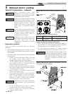
Termination and fittings
1. The air termination coupling must be oriented at least
12 inches above grade or snow line as shown in
FIG. 3-1A, page 22.
2. Maintain the required dimensions of the finished
termination piping as shown in FIG. 3-1A, page 22.
3. If using a stainless steel sidewall termination do not
extend exposed vent pipe outside of the building more
than what is shown in this document. Condensate could
freeze and block vent pipe.
4. PVC/CPVC terminations are designed to accommodate
any wall thickness of standard constructions per the
directions found in this manual.
5. Stainless steel terminations are designed to penetrate
walls with a thickness up to 9.25 inches of standard
construction.
All vent pipes and air inlets must
terminate at the same height to avoid
possibility of severe personal injury,
death, or substantial property damage.
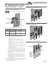
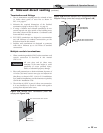
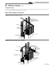
Multiple vent/air terminations
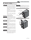
1. When terminating multiple SYNC boilers terminate each
vent/air connection as described in this manual
(FIG. 3-5A).
2. Place wall penetrations to obtain minimum clearance of
12 inches (305 mm) between vent pipe and adjacent air
inlet elbow, as shown in FIG. 3-5A for U.S. installations.
For Canadian installations, provide clearances required by
CSA B149.1 Installation Code.
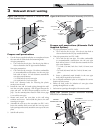
3. The air inlet of a SYNC is part of a direct vent connection.
It is not classified as a forced air intake with regard to
spacing from adjacent boiler vents.
ƽ WARNING
12" MIN. BETWEEN EDGE OF AIR
INLET AND ADJACENT VENT OUTLET
VENT / AIR
TERMINATION
VENT
AIR
Figure 3-5A Multiple Vent Terminations (must also
comply with Figure 3-1A)
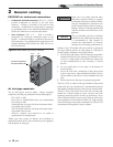
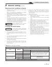
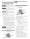
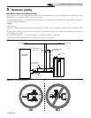
VENT
12” (305 MM) MIN
15” (381 MM) MAX
12” (305 MM) MIN. BETWEEN EDGE
OF AIR PIPE AND ADJACENT VENT
PIPE
AIR
Figure 3-5B Alternate Multiple Vent Terminations w/Field
Supplied Fittings (must also comply with Figure 3-1B)