


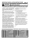
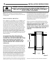
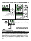
SPRINGS, PULLEYS, CABLES AND MOUNTING HARDWARE USED TO
BALANCE YOUR GARAGE DOOR ARE UNDER EXTREME TENSION AT ALL
TIMES AND CAN CAUSE SEVERE INJURY OR DEATH IF DISTURBED.
DO NOT ATTEMPT ADJUSTMENT.
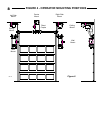
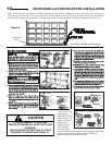
Figure 6, page 8 illustrates several positions suitable for
mounting the operator; right hand or left hand, either wall mount
or ceiling mount.
CHAIN COUPLING MOUNTING
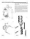
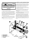
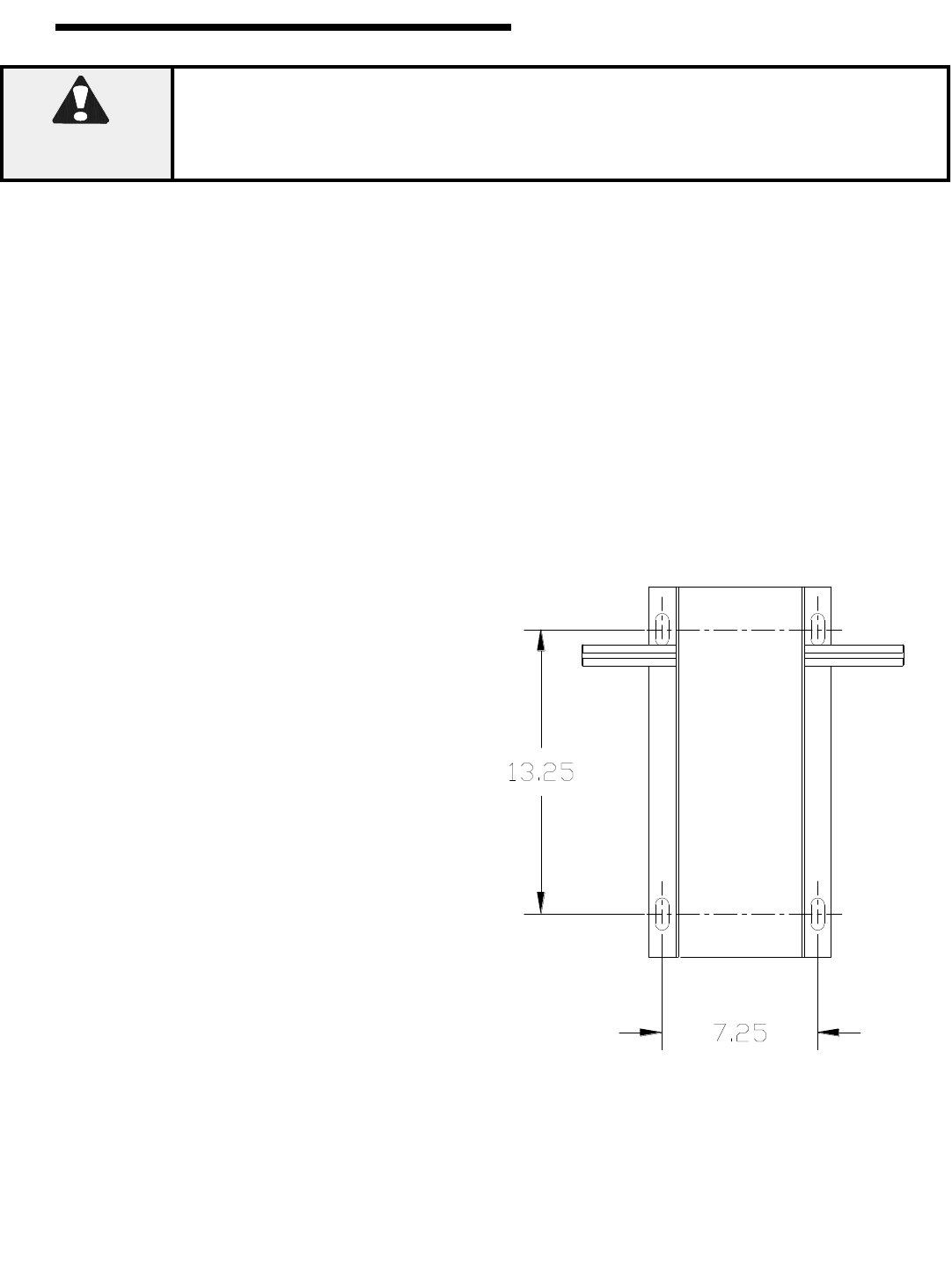
Refer to Figure 2 (at right), Figure 1, page 4 and Figure 7, page
9 for component identification and the operator mounting slot
locations. Place the sprockets [ 5 ] and [ 14 ] on the chosen side
of the torsion shaft of the door and on the corresponding end of
the output shaft of the operator, see Figure 3. The sprockets
should be kept as close as possible to the bearings. Fasten the
connecting link to each end of the door chain and loop the chain
over the sprocket [ 5 ] on the torsion shaft. Temporarily suspend
the operator in its mounting position using the chain over the
sprocket [ 14 ] at one end of the jackshaft and a rope or chain at
the mid point (to support the operator weight). With the chain
tight and straight and the jackshaft parallel with the torsion shaft,
trace the mounting slot on the mounting surface then lower the
operator to the floor.
IT IS ESSENTIAL THAT THE SURFACE
SUPPORTING THE OPERATOR BE RIGID
AND SECURE. FAILURE TO PROVIDE A FIRM
MOUNTING SURFACE WILL RESULT IN
DAMAGE TO THE DOOR TORSION SHAFT
AND THE PREMATURE FAILURE OF THE
OPERATOR.
If the construction permits, the operator should be mounted with
3/8 inch diameter bolts through the wall. If it is not feasible to go
through the wall, then use lag bolts to fasten the operator to the
mounting surface. Locate the four holes within the tracings of the
slots made in the previous step at the positions which will allow
for adjust-ment of the chain tension. After drilling the mounting
holes and instal-ling lag shields, if necessary, bolt the operator to
the mounting surface but do not completely tighten the bolts at
this time. Check the alignment of the sprockets, adjust their
positions on the shafts if necessary and tighten the set screws
securely on both sprockets. pulling downward on the operator to
remove slack from the chain, tighten the four mounting bolts.
Inspect the installation. There should be no slack in the chain but
neither should it be under severe tension which might shorten the
life of the bearings. If there is any flexibility in the system due
to construction of the surface supporting the operator or
noticeable deflection of the door shaft, it is advisable to install a
shaft support between the operator jackshaft and the door shaft
to prevent the loss of limit settings due to the possibility of the
chain jumping over the sprocket teeth. Shaft supports are
available from the factory.
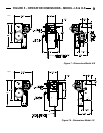
If there isn‟t a keyway on the doorshaft, keep the sprockets
aligned and drill a 5/16” hole through the door drive sprockets
and door shaft. Insert roll pin, Item (2). See Figures 3 & 4.
BEFORE PROCEEDING WITH THE
OPERATOR INSTALLATION AND SETTINGS,
MAKE A FINAL CHECK FOR TIGHTNESS OF
ALL MOUNTING HARDWARE AND SET
SCREWS.
Proceed to “Chain Hoist and Floor Disconnect Installation”.
WARNING
107851
Figure 2
6
INSTALLATION INSTRUCTIONS