


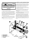

The purpose of this booklet is to provide assembly,
installation and operation information concerning Model J-S
& H-S Commercial Vehicular Garage Door Operators and
related Accessory Products.
NOTICE
IT IS IMPORTANT THAT THIS INSTRUCTION
MANUAL BE READ AND UNDERSTOOD
COMPLETELY BEFORE INSTALLATION OR
OPERATION IS ATTEMPTED. IT IS INTENDED
THAT THE INSTALLATION OF THIS UNIT WILL BE
DONE ONLY BY PERSONS TRAINED AND
QUALIFIED IN THE INSTALLATION, ADJUSTMENT
AND SERVICE OF COMMERCIAL OVERHEAD
DOORS AND DOOR OPERATORS AND BY
QUALIFIED ELECTRICIANS.
NOTICE
THE IMPORTANT SAFEGUARDS AND
INSTRUCTIONS IN THIS MANUAL CANNOT COVER
ALL POSSIBLE CONDITIONS AND SITUATIONS
WHICH MAY OCCUR DURING ITS USE. IT MUST
BE UNDERSTOOD THAT COMMON SENSE AND
CAUTION MUST BE EXERCISED BY THE PERSON
(S) INSTAL- LING, MAINTAINING AND OPERATING
THE EQUIPMENT DESCRIBED HEREIN. DO NOT
USE THIS EQUIPMENT FOR ANY OTHER THAN ITS
INTENDED PURPOSE - OPERATING OVERHEAD
COMMERCIAL VEHICULAR GARAGE DOORS.
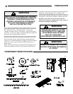
STANDARD FEATURES:
Solid State Controls: The openers employ solid state technology
with advanced standard features to provide for a complete
commercial door operating system.
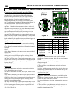
Switch Selectable Operating Modes: Six distinct base operation
modes can be selected by resetting the switches on the motor
control board: a standard Open, Close, Stop (B2, momentary
button push); three constant pressure modes (C2, D1, and E2); two
Timer to Close modes (T and TS). See page 15 for complete
description of the modes.
Switch Selectable Characteristic Modes: Five different
operating characteristics can be activated and/or modified through
the switches on the motor control board: Delay On Reverse, Close
Limit Delay, Mid Stop Travel, Timer to Close, Maximum Run
Timer.
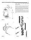
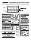
Limit Switches: Driven limit switches, easily adjusted over a
wide range. The motor may be removed without affecting the
limit switch adjustments
Manual Release: Permits manual operation of the door in the
event of a power failure. The Model H-S is equipped with a chain
hoist to aid in manual operation.
Control Circuit: Standard three button open, close and stop. 5
Volts DC.
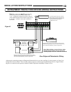
Connections For Auxiliary Entrapment Protection Devices:
For the ultimate in protection, terminals are provided to connect a
Linear Corp. Photo-Beam System that consists of an emitter, Part
No. 217792 and detector, Part No. 217800. This device when
connected is a monitored photo-beam system. Additional
connection terminals for a Normally Open and Normally
Closed reversing devices such as a reversing door edge or a
three wire photo-beam are provided.
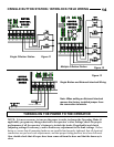
Constant Contact To Close: Standard operating mode. The
operator can be converted to Momentary Contact To Close
when the photo-beam as described above or one of the Miller
Edge family of Door Edge devices as described on this page
is properly installed on the door and connected to the
operator. See Page 10 for the entrapment protection
installation guide.
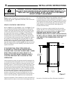
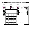
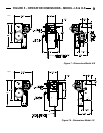
MODEL J-S & H-S OPERATOR APPLICATIONS:
Jackshaft operators are intended for commercial and industrial use
to raise or lower sectional overhead doors by chain coupling or
direct coupling to the door shaft. Jackshaft operators are suitable
where all or part of the door remains in a vertical position when
fully open such as doors with at least 18 inches of lift clearance or
full vertical lift doors. Jackshaft operators may also be used with
roll up service doors and grills when appropriately modified at the
factory to obtain the correct speeds.
A jackhaft operator DOES NOT LOCK THE DOOR IN
ITS CLOSED POSITION. However, because the cross-
header shaft is prevented by the operator from turning, the
torsion springs provide no assistance in lifting the door
should an attempt be made to raise it manually.
The J & H Series jackshaft operators are used in the
following applications:
- Continuous Duty, Medium Cycle Commercial
installations only
- Indoor Use Only
- Up to 24 foot high doors with a maximum area of 480
square feet for 3/4 HP, 280 square feet for 1/2 HP and
200 square feet for 1/3 HP - maximum area slightly
higher for lighter doors - consult factory
- To operate in Momentary Contact To Close mode and
comply with the UL325 Entrapment Protection requirements
effective Aug. 29, 2010, the door system must include one of
the following (a, b, or c):
(a) Linear Corp. Photo-Beam System that consists of an
emitter, Part No. 217792 and detector, Part No. 217800 for
doors as described above up to 30 FT wide. See Page 10.
(b) Any Miller Edge ME, MT/MU, and CPT family of edges,
with suffix T2, must be connected to the SM-102 Edge
Module, Recognized by UL as per UL325 2010 on 08-29-
2010 for door as described above. See Page 10.
(c) A Vitector Fraba OSE 2-wire Photosystem as Recognized
by UL as per UL325 2010 on 08-29-2010 for door as
described above. See Page 10.
- The manufacturer of this operator strongly recommends
installation of one of the entrapment protection device above
and states that one is REQUIRED where any automatic,
remote or manual control is used to activate the door.
OPTIONAL FEATURES:
Digital Radio Controls: Open, Close and Stop operation.
Radio units are available to control up to 27 doors from one
transmitter
Keyless Entry System: Connection terminals provided for
hard wired or wireless keyless entry systems.
PRODUCT FEATURES
3