


RISK OF ENTRAPMENT THAT MAY
RESULT IN SERIOUS PERSONAL INJURY OR
DEATH. DISCONNECT POWER TO THE
OPENER BEFORE AND DURING
INSTALLATION OF AN ACCESSORY
REVERSING DOOR EDGE OR
PHOTOELECTRIC DEVICE. DO NOT
RECONNECT POWER TO OPENER UNTIL
INSTRUCTED TO DO SO. ENSURE DOORWAY
IS CLEAR BEFORE STARTING TESTING OF
UNIT.
WARNING
TO PREVENT THE RISK OF PERSONAL INJURY
AND/OR DAMAGE TO DOOR OR PROPERTY,
ONLY OPERATE DOOR CONTROL WHEN
DOOR IS IN CLEAR VIEW. IF CONTROL
STATION CANNOT BE LOCATED WHERE THE
DOOR IS VISIBLE OR IF ANY OTHER DEVICE IS
USED TO CONTROL THE DOOR AN AUXILIARY
ENTRAPMENT DEVICE (DOOR EDGE OR
PHOTOELECTRIC) MUST BE CONNECTED.
WARNING
TO PREVENT THE RISK OF PERSONAL INJURY
OR DEATH :
• DISCONNECT POWER AT THE FUSE BOX
BEFORE PROCEEDING.
• ELECTRICAL CONNECTIONS MUST BE MADE
BY A QUALIFIED INDIVIDUAL.
• OBSERVE LOCAL ELECTRICAL CODES WHEN
WIRING THE OPERATOR.
WARNING
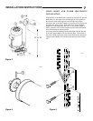
WARNING: The J-S and H-S Series operators have
been designed and constructed for use with voltages
from 115 Volts AC to 480 Volts AC, in single or three
phase. Check the operator nameplate label on the
control box cover for the proper voltage and phase. The
application of an improper input voltage or phase will
result in catastrophic failure to the internal electrical
components.
Observe local electrical codes when wiring the operator.
When hard wiring, observe state and local electrical codes. A
wiring diagram is attached to the inside of the control box cover.
Connect the appropriate voltage and phase power leads to the
appropriate terminals as per the wiring diagram and connect a
ground wire to the grounding screw. On three phase units,
incorrect phasing of the power supply will cause the motor to
rotate in the wrong direction (open when CLOSE button is pushed
and vice versa). To correct this, interchange any two of the
incoming three phase conductors.
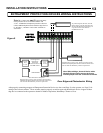
The wiring diagram attached inside the cover of the control box
details all of the field wiring terminal connections for the operator.
Always connect the wires to the push-button controls and auxiliary
devices exactly as shown.
Warning: Control voltage of the opener is 5 volts DC, Class 2.
Do not run the power leads and control circuit wiring in the same
electrical conduit.
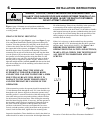
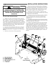
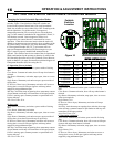
Note: J-S and H-S Series model operators are pre-wired for
entrapment protection devices. To operate in Momentary
Contact To Close mode and comply with the UL325
Entrapment Protection requirements effective Aug. 29, 2010,
an approved external entrapment device as described on Page 3
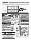
must be installed and connected to the operator. Refer to Figure
9 and the manufacturer‟s instructions to install and connect one
of the approved door edge devices. One or more contact
sensors shall be located at the bottom edge of a vertically
moving door. Refer to the instructions on Page 12 for the
Linear photoelectric system installation and wiring.
If the external entrapment protection device is connected, the
selector switches are set properly (Page 16) and the device
detects an obstruction or becomes inactive, an opening door
continues to open and a closing door stops, pauses and starts
open. While in this mode, if a problem is detected while the
operator is stopped, a close will require constant activation of
the control Close button. If an entrapment protection device as
described above is attached and is properly working for 1
second, it will be auto detected and the monitored function will
be turned on. Once the monitoring function is active, it will
remain active even if the power is removed and the entrapment
protection device is disconnected and power is restored. While
in this mode, if a problem is detected while the operator is
stopped, a close will require constant activation .
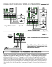
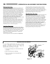
Operators which have an operational entrapment protection
device as described above may have one or more additional
means of control which should be wired in accordance with the
diagram supplied in the opener and also illustrated on Pages 20
& 21. To add a second three button station, refer to Figure 12.
Number 22 gauge wire or heavier must be used for wiring
the control stations and auxiliary control devices to the
operator. Smaller gauge wire will cause operational
problems, especially when multiple push-button stations are
used or during summer months.
INSTALLATION INSTRUCTIONS
11