


4) Depress the limit nut retaining Plate (D) so it disengages
from the slots in the limit nuts. Turn the OPEN limit nut (E) on
the shaft until it engages the Open Limit Switch (A). You will
need to listen for an audible click. Release the retaining plate
and be sure that it engages in slots of both limit nuts.
5) Manually lower the door to approx. 4 inches shy of the
fully closed position and repeat Step #4 with the Close Limit nut
(C) and the Close Limit switch (B).
6) Manually move the door to a half open position. With the
door in a mid position there will be time to stop the door if
something or someone were in the door path when initially
starting the door.
7) An additional limit adjustment may be necessary after the
connection of the power supply in order to ensure the door stops
at the proper Open and Close positions.
8) If needed, a fine adjustment of the Close Limit switch (B)
or Open Limit switch (A) is possible by loosening the screws
slightly that hold the switch to the V bracket and moving the
switch within its mounting slots. Ensure to retighten the switch
mounting screw. Moving the Reverse Cutout switch closer to
the center of the box will increase the point where the reversing
feature cuts out (to allow for irregularity in the floor, etc.). The
reverse cutout point is factory adjusted to approx. 4 inches off
the floor.
TO AVOID RISK OF ENTRAPMENT AND
POSSIBLE DAMAGE TO THE DOOR AND
OPERATOR THE LIMITS MUST BE ADJUSTED
BEFORE APPLYING POWER TO THE
OPERATOR.
WARNING
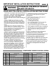
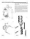
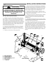
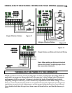
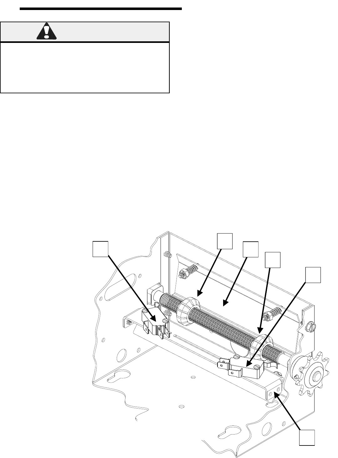
A - OPEN LIMIT SWITCH
B - CLOSE LIMIT SWITCH
C - CLOSE LIMIT NUT
D - LIMIT NUT RETAINING PLATE
E - OPEN LIMIT NUT
F - “V” BRACKET
A
113116
B
E
C
D
F
Figure 8
Limit Assembly
SETTING THE LIMIT SWITCHES
1) With the cover open on the electrical enclosure, reference
Figure 8 below. There are two (2) switches (A and B) mounted to
the „V‟ bracket (F). The Close Limit switch (B) and the Open
Limit switch (A) are mounted to the top side of the „V‟ bracket as
shown. These switches are activated by the two limit nuts (E & C)
on the threaded shaft which move laterally along the shaft as the
operator opens and closes the door. When a limit nut nears the
end of the shaft it activates a switch.
2) Depress the Limit Nut Retention Plate (D) so it disengages
from the slots in the limit nuts and move the Limit nuts to the
center of the threaded shaft. Re-engage the Limit Nut Retention
Plate (D).
3) Manually raise the door to a fully open position.
10
INSTALLATION INSTRUCTIONS