


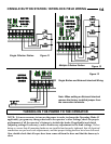
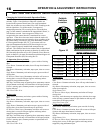

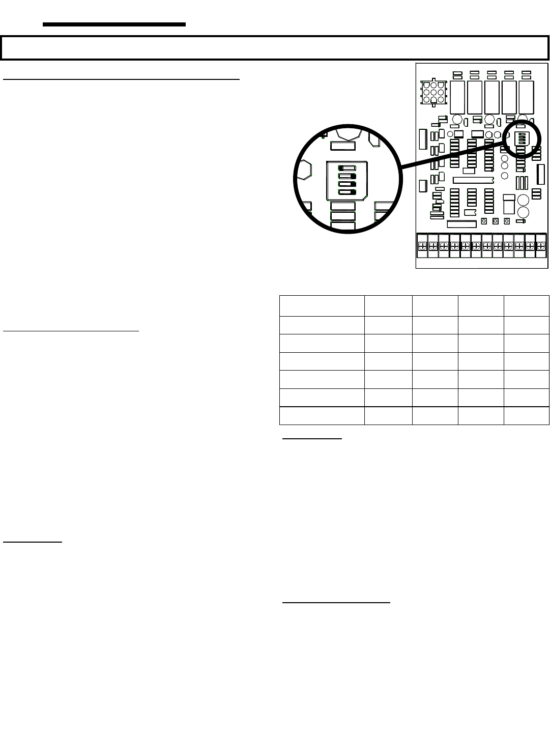
Changing the Switch Selectable Operation Modes
The following modes are selected by setting the on-board dip
switches, Figure 14 at right shows where the switches are
located on the operator control board. For each Operational
Mode, the switches are set to either ON or OFF according to the
table at right below. For all the modes, if an approved
entrapment protection (EP) reversing device as described on
page 3 of this manual is attached to the input labeled “Photo”, it
will function as noted. Once an approved EP device is
recognized by the control board it is monitored for correct
operation. If the device becomes inactive then the mode will
default to constant pressure activation for close regardless of the
dip switch setting. In order for any of the Momentary Contact
to Close operation modes (B2, TS, T) to become active an
approved Entrapment Protection (EP) Reversing device (see
Page 3) must be properly installed and connected to the
operator. The switches must be set to one of the six Operational
Mode combinations for the operator to function. It order for the
NO (Normally Open) Reverse or NC (Normally Close) Reverse
inputs to function, you must first install an operational approved
Entrapment Protection (EP) Reversing Device.
C2 Operation (Factory default)
Open Button: Momentary activation; open override of closing
door.
Close Button: Constant activation, door will stop when button is
released.
Stop Button: Momentary activation; stops open, close or reverse
action.
Single Button: Momentary activation to open; open override of
closing door.
EP Reverse (Photo Input): Momentary activation will reverse a
closing door, reverse to full open (ignores mid-stop) unless
stopped by stop pushbutton input.
Mid-Stop: Activation stops an opening door; momentary contact
of open button at mid stop will restart door to full open position;
if door is moving open, constant pressure on open button will
bypass mid-stop.
Auto Close Timer: N/A.
B2 Operation
Open Button: Momentary activation; open override of closing
door.
Close Button: Momentary activation.
Stop Button: Momentary activation; stops open, close or reverse
action.
Single Button: Momentary activation to open; open override of
closing door, closes door from mid-stop or open limit.
EP Reverse (Photo Input): Momentary activation will reverse a
closing door, reverse to full open (ignores mid-stop) unless
stopped by stop pushbutton input.
Mid-Stop: Activation stops an opening door; momentary contact
of open button at mid stop will restart door to full open position;
if door is moving open, constant pressure on open button will
bypass mid-stop.
Auto Close Timer: N/A.
D1 Operation
Open Button: Constant activation; open override of closing
door.
Close Button: Constant activation, door will stop when button is
released.
Stop Button: Momentary activation; stops open, close or reverse
action (not required).
Single Button: N/A.
EP Reverse (Photo Input): Momentary activation will stop a
closing door.
Mid-Stop: Activation stops an opening door; after the door stops
at the mid stop, constant contact of open button at mid stop will
restart door to full open position.
Auto Close Timer: N/A.
E2 Operation (roll-back)
Open Button: Momentary activation; open override of closing
door.
Close Button: Constant activation, door will reverse to full open
(ignores mid-stop) when button is released.
Stop Button: Momentary activation; stops open, close or reverse
action.
Single Button: N/A.
EP Reverse (Photo Input): Momentary activation to reverse a
closing door, reverse to full open (ignores mid-stop) unless
stopped by stop pushbutton input.
CDOMCB 2005
EDGE
RADIO
c.p. ALLSTAR CORP.
P4
24V
S1
R58
R56
R55
R54
R45
R46
R53
PCB 112695 REV B TSLK
K2K4K3K5
K6
COM
OLS
CLS
COM
HIGH VOLTAGE
OPEN
MO4
MO3
MO2
MO1
ILK
24V
COM
VCC
FRA
COM
24V
RM1
RM2
RM3
VCC
COM
P7
R8
R24
C12
TB1
STATUS
LD4
OFF
S4
S3
S2
S1
C25
R94
R87
R38
R22
R10
P5
PB1 PB2 PB3
R49
C6
R93
R90
U5
R62
R61
R60
R5
R25
R9
R23
R51
R19
R17
R13
R20
R18
R14
STOPCLOSEOPEN
R7R6
R16R15
R11 R12
POWER
C24
R85
U1
C2
RO1
D8
U4
C11
R30
R26
R29
C3
C1 C8
R47
R84
R95
SW1
R83
R82
R33
R34
R2
R3
R4
C21
R21
D2
R65
C10
D3
C9
TR4
TR2
R52
C14
TR1
R48
C13
TR3
R89
Q1
C7
D1
D12
R28
R27
C16
LD3
LD2
P2 P3
R1
C30
P1
R31
P6
R57
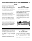
COM
CLOSE
STOP
NO REV
NC REV
PHOTO
COM
SINGLE
ILOCK
24 VAC
COM
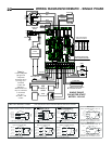
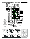
MOTOR CONTROL BOARD
CDOMCB 2005
EDGE
RADIO
c.p. ALLSTAR CORP.
P4
24V
S1
R58
R56
R55
R54
R45
R46
R53
PCB 112695 REV B TSLK
K2K4K3K5
K6
COM
OLS
CLS
COM
HIGH VOLTAGE
OPEN
MO4
MO3
MO2
MO1
ILK
24V
COM
VCC
FRA
COM
24V
RM1
RM2
RM3
VCC
COM
P7
R8
R24
C12
TB1
STATUS
LD4
OFF
S4
S3
S2
S1
C25
R94
R87
R38
R22
R10
P5
PB1 PB2 PB3
R49
C6
R93
R90
U5
R62
R61
R60
R5
R25
R9
R23
R51
R19
R17
R13
R20
R18
R14
STOPCLOSEOPEN
R7R6
R16R15
R11 R12
POWER
C24
R85
U1
C2
RO1
D8
U4
C11
R30
R26
R29
C3
C1 C8
R47
R84
R95
SW1
R83
R82
R33
R34
R2
R3
R4
C21
R21
D2
R65
C10
D3
C9
TR4
TR2
R52
C14
TR1
R48
C13
TR3
R89
Q1
C7
D1
D12
R28
R27
C16
LD3
LD2
P2 P3
R1
C30
P1
R31
P6
R57
COM
CLOSE
STOP
NO REV
NC REV
PHOTO
COM
SINGLE
ILOCK
24 VAC
COM
Figure 14
Settable
Switches
Location
Operating Mode Switch 1 Switch 2 Switch 3 Switch 4
C2 Operation OFF OFF OFF OFF
B2 Operation ON OFF OFF OFF
D1 Operation OFF ON OFF OFF
E2 Operation ON ON OFF OFF
TS Operation OFF OFF ON OFF
T Operation ON OFF ON OFF
SETTING THE SWITCH SELECTABLE OPERATING MODES
OPERATION & ADJUSTMENT INSTRUCTIONS
16