


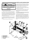

MOTOR
CONTROL
BOARD
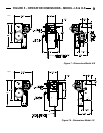
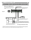
Figure 9
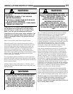
OPEN
TB1
STOPCLOSEOPEN
COM
CLOSE
STOP
NO REV
NC REV
PHOTO
COM
SINGLE
ILOCK
24 VAC
COM
SAFE FINISH PHOTOBEAM
3-WIRE PHOTOBEAM
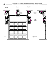
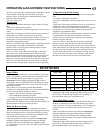
Door Edge and Photoelectric Wiring
After properly connecting an approved Entrapment Protection Device (see above and Page 3) to the operator, see Page 15 for
setting of the selector switches. These switches must be properly set and an approved photoelectric device or approved door
edge device connected to the operator to obtain B2 Mode of Operation, Momentary Contact to Close.
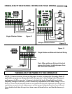
Linear Approved
Photoelectric
Entrapment
Protection Device
See Note A above
Emitter
Part #
217792
Detector
Part #
217800
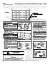
3 Wire Photoelectric Entrapment
Protection Device wiring. Note: This device can be used for
additional Entrapment protection but connection of this device
will not enable the Momentary Contact to Open Mode.
Any Miller Edge ME, MT/MU, and CPT
family of edges, must be connected to the
SM-102 Edge Module, Recognized by UL
as per UL325 2010 on 08-29-2010.
See Note A to the left.
2 Wire Door Edge
Protection Device wiring. Note: This device can be used for
additional Entrapment protection but connection of this device
will not enable the Momentary Contact to Open Mode.
Note A: Connect only one (1) approved entrap-
ment protection device to terminals “Photo” and
“Com”. If additional entrapment protection is desired
connect additional photoelectric and door edges devices
to “NC REV”, “NO REV” and “COM” terminals as
shown here.
Note: When adding a photocell device with a
Normally Closed output remove the factory
installed jumper from the connection terminals.
OPEN
TB1
STOPCLOSEOPEN
COM
CLOSE
STOP
NO REV
NC REV
PHOTO
COM
SINGLE
ILOCK
24 VAC
COM
SAFE FINISH PHOTOBEAM
3-WIRE PHOTOBEAM
ENTRAPMENT PROTECTION DEVICES WIRING INSTRUCTIONS
13
INSTALLATION INSTRUCTIONS