


READ THESE STATEMENTS CAREFULLY AND FOLLOW THE
INSTRUCTIONS CLOSELY.
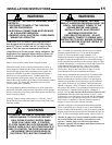
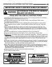
The Warning and Caution boxes throughout this manual are there to protect you and your
equipment. Pay close attention to these boxes as you follow the manual.
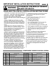
WARNING
Indicates a MECHANICAL
hazard of INJURY OR
DEATH. Gives instructions
to avoid the hazard.
CAUTION
Indicates a MECHANICAL hazard
of DAMAGE to your operator or
equipment. Gives instructions to
avoid the hazard.
Indicates an ELECTRICAL
hazard of INJURY OR
DEATH. Gives instructions
to avoid the hazard.
WARNING
Indicates an ELECTRICAL hazard
of DAMAGE to your operator or
equipment. Gives instructions to
avoid the hazard.
CAUTION
Product Features........................................................................................................... 3
Jackshaft Operator Applications ................................................................................. 3
Preparation .................................................................................................................... 4
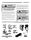
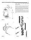
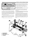
Figure 1 - Component Identification Pictorial ............................................................. 4
Important Installation Warnings (Things To Do Before & During Installation) ......... 5
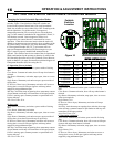
Table 1 - Component Identification Listing ................................................................. 5
Installation Instructions ........................................................................................... 6-13
Figure 2 - Operator Footprint - J-S / H-S ..................................................................... 6
Figure 5 - Release/Hand Chain Wall Bracket Installation ........................................... 7
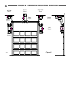
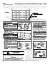
Figure 6 - Mounting Positions ...................................................................................... 8
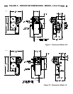
Figure 7 - Operator Dimensions - Model H-S ............................................................. 9
Figure 7A - Operator Dimensions - Model J-S ........................................................... 9
Setting The Limits ....................................................................................................... 10
Figure 8 - Limit Adjustment ........................................................................................ 10
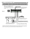
Electrical Wiring Instructions ..................................................................................... 11
Figure 9 - Door Edge Installation ............................................................................... 12
Safety Beam Photoelectric Entrapment Protection Device Installation .................. 12
Figure 10 - Door Edge and Photoelectric Wiring ...................................................... 13
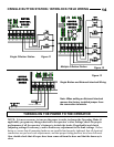
Figures 11-13 Field Wiring ......................................................................................... 14
Turning On Power to the Operator............................................................................. 14
Operation and Adjustment Instructions ............................................................... 15-19
Important Safety Instructions for Owner ................................................................... 15
Switch Selectable Operating Modes .......................................................................... 16
Operating Characteristics Setup Modes ................................................................... 17
Brake Adjustment ....................................................................................................... 18
Clutch Adjustment ...................................................................................................... 19
Safety Beam Photoelectric Entrapment Protection Device Adjustment ................. 20
Testing ......................................................................................................................... 21
Maintenance ............................................................................................................... 21
Wiring Diagram - Single Phase .................................................................................. 22
Wiring Diagram - Three Phase ................................................................................... 23
Parts Identification ...................................................................................................... 25
Operator Specifications .............................................................................................. 26
Warranty ...................................................................................................................... 26
TABLE OF CONTENTS
2