


- 37 -
Copyright ©2008 LG Electronics. Inc. All right reserved.
Only for training and service purposes
LGE Internal Use Only
Note:
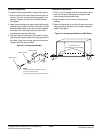
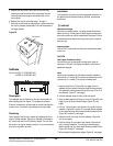
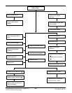
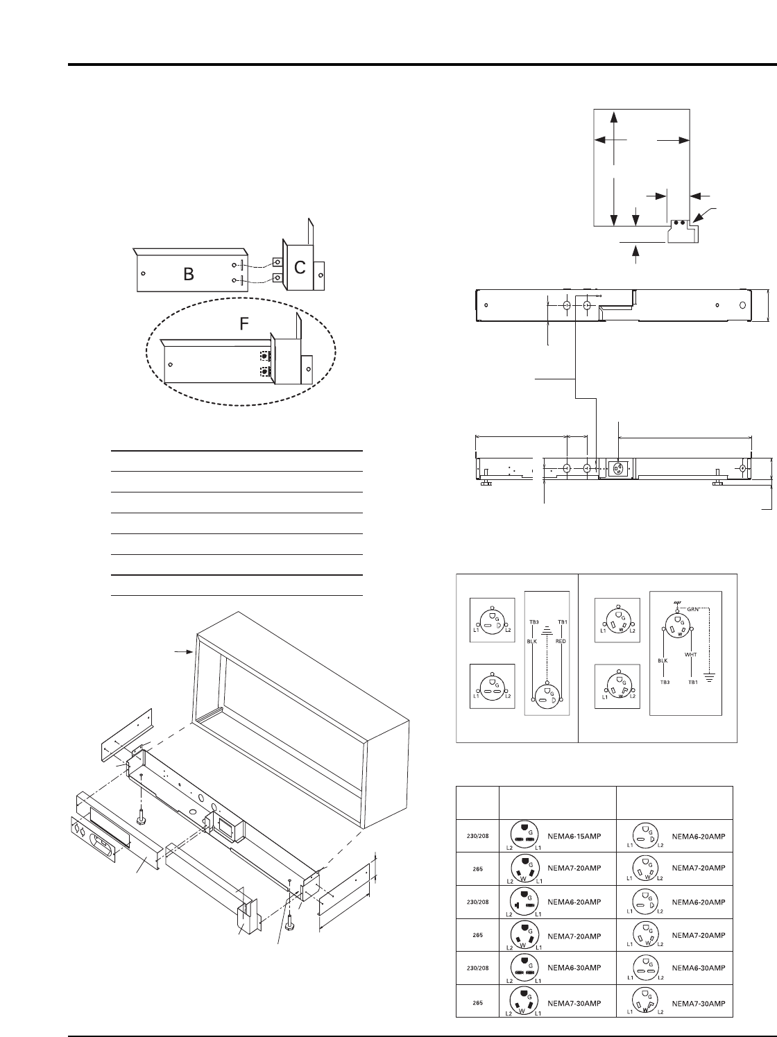
The proper subbase must be ordered to obtain the correct
electrical receptacle. (Figure 61)
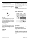
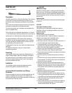
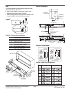
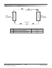
8. After wiring is complete, mount covers A and F to the
subbase with provided screws. (Figure 58)
9. When installing optional accessories to the subbase, refer
to each installation instruction for that accessory.
Figure 57
Part/Location Identification
A
B
C
D
E
F
Left Front Cover
Right Front Cover
Front Cord Panel
Wall Sleeve Hole Location
Skirting Hole Location
Right Cover Assembly
Wall Sleeve
Cover
Wiring
Access
Subbase
Box Assembly
Low Voltage
Compartment
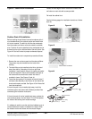
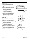
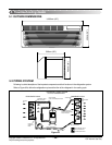
2-13/16"
(71 mm)
11-13/16"
(300 mm)
A
B
F
C
E
D
D
E
Wall Sleeve
(Outdoor Side)
Wall Sleeve
Inside Edge
Back of
Flange "A"
13 3/4"
2 3/4"
2 5/8"
13-7/8" (352 mm)
3-1/16"
(78 mm)
Left End View
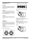
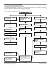
Concentric
Knockouts In Bottom
Ground
Screw Location
Receptacle Provided
Inside subbase
Accessory
Top View
Concentric
Knockouts In Rear
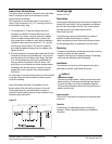
Field Wiring
Line Voltage
Field Wiring
Line Voltage
NEMA 6-20R
Receptacle
230/208 VAC Field Schematic 265 VAC Field Schematic
NEMA 6-30R
Receptacle
Voltage Subbase ReceptacleUnit Plug
NEMA 7-30R
Receptacle
NEMA 7-20R
Receptacle
Front View
20-5/16" (515.5 mm)
2" (50 mm) Max.
Adjustment
4" (101 mm)
2-5/8" (67 mm)
2" (50 mm)
2 3/4"
16"
16"
1-3/8" (35 mm)
Figure 58 - Part/Location Identification
Figure 59 - Dimensions
Figure 60 - Wiring Diagram
Figure 61 - NEMA Plug Configurations